


Manual
COMPACT
7
‐
225
Revision
4
F.2a
(ENG)
INSTALLATION
AND
OPERATION
INSTALLATION
REQUIREMENTS
COMPACT
air
Dryers
Should
be
located
indoors
in
an
area
where
the
ambient
temperature
is
not
likely
to
exceed
43°C
or
be
less
than
0
°C.
For
locations
where
this
maximum
ambient
temperature
is
exceeded
for
prolonged
periods
of
time
a
water
cooled
condenser
and/or
high
ambient
kit
is
fitted
as
option.
IMPORTANT
Compressed
air
should
not
be
passed
through
the
dryer
when
it
is
inoperative.
Protect
the
dryer
with
automatic
bypass
and
outlet
valves
when
the
dryer
is
part
of
an
automatic
system.
When
operating
the
air
inlet
should
not
exceed
55°C
assuming
the
dryer
is
sized
for
this
inlet
temperature.
Make
sure
the
externally
fitted
compressed
air
inlet
and
outlet
pipes
are
sufficiently
supported
in
order
to
avoid
that
they
become
a
gravity
load
on
the
Dryer’s
inlet
‐
and
outlet
connexions
The
maximum
air
pressure
should
not
exceed
16
bar(g).
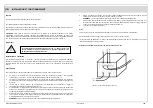
INSTALLATION
The
COMPACT
compressed
air
dryer
should
only
be
fitted
by
competent,
properly
trained
and
skilled
installers.
It
is
recommended
that
for
most
compressed
air
applications
the
installation
is
arranged
as
shown.
This
arrangement
can
help
to
ensure
optimum
performance
of
the
compressor,
filters
and
dryer
and
this
ensures
optimum
air
quality
and
minimum
operating
costs.
The
compressed
air
inlet
should
not
contain
corrosive
components,
which
can
corrode
the
copper
piping
and
connecting
pieces
in
the
COMPACT
Dryer.
The
immediate
surroundings
of
the
Dryer
should
also
be
free
of
corrosive
substances.
Corrosive
substances
are
amongst
others,
ammonia
&
ammonium
derivates,
acetylene,
chlorine
derivates,
hydrogen
peroxide,
acids
and
salts
in
general
(if
in
doubt
concerning
corrosive
substances,
contact
MCIB
Air
Dryers
representative).
If
the
system
is
going
to
be
subject
to
large
instantaneous
flows
exceeding
the
“sized”
capacity
of
the
dryer,
then
the
outlet
of
the
dryer
should
have
a
flow
control
orifice
installed
to
protect
the
dew
point
or
better
still
a
suitably
sized
receiver
next
to
the
source
of
the
overload.
Every
pressure
vessel
or
accessory
installed
externally
to
the
dryer
holding
air
at
above
atmospheric
pressures,
must
be
protected
with
the
necessary
pressure
release
systems.
The
Dryer
must
be
sufficiently
clear
of
walls
and
adjoining
equipment
so
that
the
access
panels
may
be
easily
removed
for
maintenance
and
to
provide
a
free
circulation
of
air
through
the
ventilating
louvers
and
grills.
Make
sure
that
there
is
sufficient
space
on
the
ventilation
air
intake
and
outlet
side.
A
minimum
of
500
mm
should
be
allowed.
Locate
the
dryer
carefully
so
that
it
is
protected
as
well
as
possible
from
ambient
temperature
influences
(e.g.
hot
exhaust
air
from
the
compressor)
A
special
base
or
foundation
is
not
necessary
when
the
floor
on
which
the
unit
will
be
installed
is
level.
The
Dryer
may
be
levelled
by
placing
shims.
The
COM
7
through
16
can
be
either
“wall
mounted”
or
“floor
mounted”.
COM
20
and
above
are
“floor
mounted”
units...
PIPING
CONNECTIONS
The
diameter
of
the
connected
air
lines
must
be
the
same
as
the
diameter
of
the
air
connections
of
the
dryer
in
order
to
keep
pressure
drops
to
a
minimum.
The
COMPACT
air
dryers
are
designed
with
internal
separator
to
remove
condensate.
A
drain
line
must
be
installed
directly
to
the
COMPACT
Dryer
drain
connection.
It
is
preferable
to
have
a
sight
glass
or
open
funnel
arrangement
to
visually
check
the
flow
of
condensate
under
operating
conditions.
Piping
with
a
diameter
of
a
least
6
mm
should
be
used
for
the
drain
outlet.
Make
sure
that
the
outlet
the
pipe
is
never
below
the
level
of
water
in
the
tank.
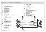
Figure
F1
Recommended
Piping
Arrangements
A
Compressor
B
Receiver
C
1
micron
filter
D
COMPACT
air
dryer
E
0.1
micron
filter
F
To
compressed
air
ring
main
G
To
open
drain
for
condensate
H
Simple
Tap


