


Chapter:
Performing Patching Activities
3–15
Tracing a Patch Connection Between an iPatch Panel Port
and Equipment
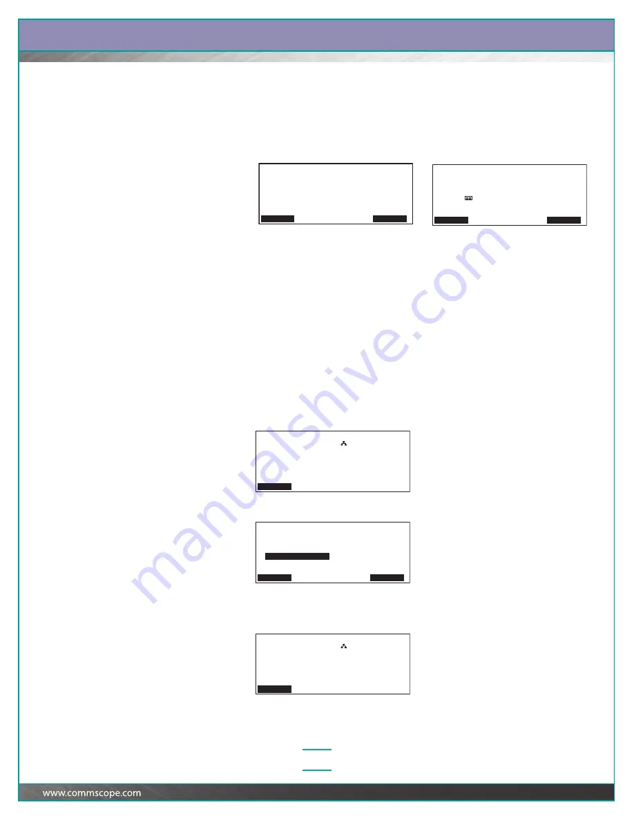
Press the button associated with the iPatch Panel port used in the connection.
The LED associated with the iPatch Panel port turns on and the display shows:
You can press Details to view more information about the connection, such as the
location of the jack where the service is provided or the type of service provided.
Press
Ê
to scroll through the information. Then, press Back to return to the Trace
screen.
Note:
When a trace is active, the Trace LED turns on at the iPatch Manager units for
the patch connection.
Tracing and Changing a Patch Connection
An incorrect connection might have been recorded if a technician did not follow the
instructions on the display or if two technicians were adding patch connections at
the same time. The Trace and Change feature lets you trace the connection
recorded for a port and identify the correct connection if the information shown for
the trace is incorrect.
1
At the iPatch Manager display, press any button to turn on the lighting. From
the Ready screen, press Menu.
2
Press
Ê
until the iPatch Manager display shows:
3
With Trace and Change highlighted, press Select.
The display shows:
or
Tracing Connection Rack 1
Rack 1 | Rack 3
Panel 5 | Server 1
Port 7 | Card 1
| Port 19
Details Exit
Tracing Duplex Connection Rack 1
Rack 1 | Rack 1
Panel 5 | Switch 1
Port 7 | Card 1
| Port 9
Details Exit
Rack 1
Ready
Menu
Alarms
Jobs
Reset Panels
Reset Racks
Clear Memory
Change Network Settings
s
Trace and Change
Highlight a command. Then press Select.
Select Exit
Rack 1
Ready
Menu
Alarms
Jobs


