
40
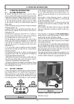
6.3.
BRUSH ASSEMBLY / DISASSEMBLY
•
Never use the machine if the brush or the pad
holder with abrasive pad is not perfectly installed.
Assembly:
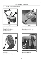
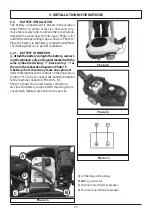
Place the brush on the floor;
lift the squeegee using the lifting/lowering lever (
Photo 2 - B )
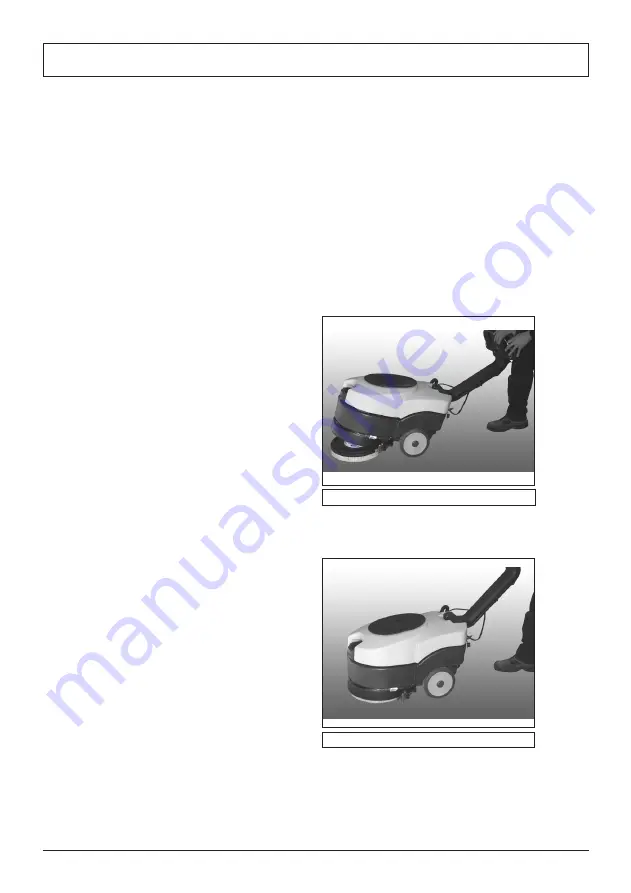
Holding the handlebar ( Photo 1 - A ) push it down-
ward in order to lift the front part of the machine by
rotating it on the rear wheels;
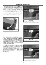
move the machine and place it over the brush, taking
care that the coupling flange on the brush is under
the metal coupling of the machine ( Photo 20 ).
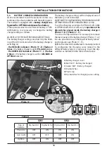
Switch on the machine using the key switch ( Photo
8 - A ) or the general ON/OFF switch on the control
panel ( Photo 5 - A ).
Select the brush rotation with the brush switch (
Photo 5 - D ; Photo 7 - C ) and start the brush rotation
pulling the control lever ( Photo 2 - A ): the brush will
couple automatically.
To assemble the pad holder follow the same procedure.
•
Do not allow the length of the rows of brushes to
become lower than 1 cm.
•
Do not allow the thickness of the abrasive disks to
become less than 1 cm.
Working with excessively worn brushes or excessively
thin abrasive disks may damage the machine and the
floor.
Regularly check the wear on these parts before start-
ing to work.
Disassembly or replacement:
Lift the squeegee using the lifting/lowering lever (
Photo 2 - B )
Holding the handlebar ( Photo 1 - A ) push it down-
ward in order to lift the front part of the machine by
rotating it on the rear wheels;
Select the brush rotation with the brush switch ( Photo
5 - D ; Photo 7 - C ) and start the brush rotation pull-
ing the control lever ( Photo 2 - A ) while holding the
machine lifted up; release the control lever to stop the
rotation: the brush will unhook automatically.
To disassemble the pad holder follow the same pro-
cedure.
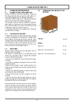
Photo 20
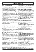
Photo 21
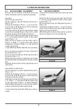
6.4.
MACHINE TRANSPORT
To transport the machine while not working, proceed
as follows:
Switch OFF the machine using the key switch ( Photo
8 - A ) or the general ON/OFF switch on the control
panel ( Photo 5 - A ).
lift the squeegee using the lifting/lowering lever (
Photo 2 - B ).
Holding the handlebar ( Photo 1 - A ) push it down-
ward in order to lift the front part of the machine by
rotating it on the rear wheels;
While holding the machine in this position, push it to
the new working area or to the parking area.
6. OPERATING INFORMATIONS
Summary of Contents for CPS 36 BX
Page 148: ...148...
Page 149: ...149...
Page 150: ...150...
Page 151: ...151...
Page 152: ...152...
Page 153: ...153...
Page 154: ...154...
Page 155: ...155...
Page 157: ...157 1 1 1 1 1 2 2 10 1 3 1 4...
Page 158: ...158 1 2 1 5 2 2 1 m 4 C e 35 C 10 50 30 95 2 10...
Page 159: ...159 2 2 2...
Page 160: ...160 3 3 1 3 2 3 3 3 3 4 0 38 61 DC 12V 70 DC 12V 50 82 cm 56 cm 8 2 c m...
Page 161: ...161 4 4 1 4...
Page 162: ...162 162 B A C D B A B A B C D 1 2 B A C A B A B A B C 4 3 4 4 2 A...
Page 163: ...163 B A C A B C A B A B C DC 12V DC 12V B A C D A B C D AC 7 5 AC A 8 6 A 4 C...
Page 164: ...164 69 101 79 114 47 4 4 3 104 81...
Page 165: ...165 5 A 5 5 1 9 10 11 12 9 10 11 12...
Page 166: ...166 5 2 14 4 13 14 5 2 1 15 16 B 16 13 14 B 5 15 16 D C A A 12V B C D...
Page 168: ...168 6 6 6 1 7 2 7 5 2 7 9 6 2 19 18 A 1 18 C 18 19 A A B A B C B...
Page 169: ...169 8 7 6 3 2 1 20 8 5 5 D 7 2 1 1 2 1 5 D 7 2 6 20 21 6 4 8 5 2 1 20...
Page 171: ...171 6 C C A A B B B B D D 24 25 A B C D 6 7 7 5 24 24 B 24 A 25 A 24 C 24 D 24 B 24...
Page 172: ...172 6 8 50 C 1 D 1 28 2 A A 28 A 29 A 6 29 A 6 9 1 D 1 B 3 B 4 13...
Page 173: ...173 A 30 A 6 30 A 3 C 30 A 6 10 31 33 2 5 C 7 B 5 D 7 C 31 32 33...
Page 175: ...175 6 7 13 3 6 12 5 7 10 6 13 AC DC 12V AC...
Page 176: ...176 7 7 1 50 7 2 29 A 7 3 23 7 4 7 5 7 6 7 7 7...
Page 177: ...177 3 AGM 6 7 8 16 16 D 7 9 7 9 1 7 9 2 7 9 3 7 10 8...
Page 178: ...178 8 8 1 1 8 2 8 3 8 4 8 5 8 6 8 7 8 8 8 9 100 8...
Page 179: ...179 20 30 8...
Page 180: ...180 9 9 12 9 1 2013 56 EU 9 2 2012 19 EU 2012 19 EU...
Page 218: ...218 69 101 79 114 47 4 TEKNISETTIEDOT 4 3 MITAT Kaikki mitat on ilmaistu senttimetriss 104 81...
Page 242: ...242 69 101 79 114 47 4 TEKNISK INFORMATION 4 3 M TT Alla m tt anges i centimeter 104 81...
Page 312: ...312 69 101 79 114 47 4 INFORMA IITEHNICE 4 3 DIMENSIUNI Toate dimensiunile sunt n mm 104 81...
Page 336: ...336 69 101 79 114 47 4 TEKN K B LG LER 4 3 EBATLAR cm 104 81...
Page 401: ...1 401 1 1 1 1 2 2 10 1 3 1 4 1 5...
Page 402: ...2 402 2 2 1 4 C 35 C 10 C 50 C 30 95 2 10...
Page 403: ...2 403 2 2...
Page 404: ...3 3 1 3 2 3 3 3 404 4 4 0 38 3 61 kg D 12V 70 kg D 12V 50 kg 82 cm 56 cm...
Page 405: ...4 405 4 4 1...
Page 406: ...406 B A C D B D 1 2 B A C A B B C 4 3 4 4 2 A...
Page 407: ...407 B A C A B C A B DC 12V DC 12V B A C D A B C D AC 7 5 AC A 8 6 4 C...
Page 408: ...408 69 101 79 114 47 4 4 3 104 81...
Page 409: ...409 5 A 5 5 1 9 10 11 12 9 10 11 12...
Page 410: ...410 5 2 14 4 B 13 14 5 2 1 15 0 16 B 16 13 14 B 5 15 16 D C A 12V D...
Page 413: ...413 8 7 6 3 2 1 20 8 A 5 A 5 D 7 C 2 A 1 cm 1 cm 2 1 5 D 7 C 6 20 21 2 A 6 4 8 A 5 A 2 1...
Page 414: ...6 5 22bis E 22 A 22 23 B 6 6 23 B 22 6 414 22 bis A D E F G H A B E D E F H C 22 23 B A B B G...
Page 415: ...415 6 6 7 7 5 24 A 24 B 24 25 C C A A B B B B D D 24 25 A D 24 24 D 24 B 24 A...
Page 416: ...416 6 8 50 C 1 1 D 28 A 2 A A 28 29 A 6 29 A 6 9 3 1 1 D 3 4 B 13...
Page 417: ...417 A 30 A 6 30 A 3 C 30 A 3 C 6 10 31 33 2 5 C 7 B 5 D 7 C ON 31 32 33...
Page 419: ...419 6 7 7 13 3 6 12 5 7 10 6 13 7 7 1 50 7 2 29...
Page 420: ...420 7 3 23 7 4 7 5 7 6 7 7 Pb 3 AGM 6 7 8 16 16 D 7...
Page 421: ...421 7 9 7 9 1 Pb 7 9 2 Pb 7 9 3 7 10 7...
Page 422: ...422 8 8 1 8 2 8 3 8 4 8 5 8 6 8 7 8 8 8 9 100 8...
Page 423: ...423 8 9 20 30 9 12 9 1 2013 56 9 2 WEEE 2012 19 EU 2012 19 EU...
Page 425: ......
Page 427: ......
Page 430: ...7 504 0290 rev 04 09 2021...