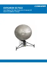
Description of the system components
98-143492-D
Chapter 2: Introduction
2-3
Introd
ucti
on
2.2
Description of the system components
2.2.1
Antenna positioner
The auto-deploy antenna positioner can accommodate 4° to 83° of angular movement in
the elevation axis and ±90° in the azimuth axis. The mechanical assemblies rely on two
independent axes to allow for precise antenna pointing. A ground gradient of up to 8° can
be accommodated with the terminal’s levelling features. The antenna positioner can stay
outside in rainy weather.
2.2.2
RF assembly
The RF assembly includes the BUC, LNB, reflector hub, filter/polarizer, and feed horn. It also
contains brackets that are attached to mounting blocks on the elevation arms. Once the RF
assembly is mounted, the thumbscrews beneath the blocks hold the brackets securely in
place. Also, the BUC and LNB are mounted closely to the filter/polarizer to reduce the need
for wave guides. This design allows for quick assembly and disassembly of the RF assembly
from the positioner.
2.2.3
Reflector
The 75 cm reflector consists of four interchangeable panels and a center hub. The panels
are made entirely of composite with the exception of the latches. The aluminum latches are
used to secure the panels to the hub. Two smaller latches along the edge of the panels
attach the reflector panels to each other. The reflector weighs 3 kg (8.5 lbs). The reflector
has been designed to meet wind load and thermal distortion requirements; see
Note
If the look angle is less than 12 degrees it is important to level the terminal.
Figure 2-3: RF assembly


