c l i m a t e m a s t e r.c o m
55
TSM/TSL Vertical Stack
R e v. : J a n u a r y 1 8 , 2 0 2 1
T H E S M A R T S O L U T I O N F O R E N E R G Y E F F I C I E N C Y
Thermostat Installation
Table 6 below lists recommended wire sizes and lengths
to install the thermostat. The total resistance of low-
voltage wiring must not exceed 1 ohm. Any resistance
in excess of 1 ohm may cause the control to malfunction
because of high voltage drop.
A91558 Series Thermostats
have 6” (152) pigtail ending
with 9-pin Molex. This allows an easy connection to either
surface mount or remote with factory whip option.
AT Series Thermostats
have to be wired to screw
terminals under the cover.
Installation of Optional Wall-Mounted Thermostat -
The unit can be furnished with a 24-volt surface mounted
ACO or MCO control circuit or a remote 24-volt ACO or
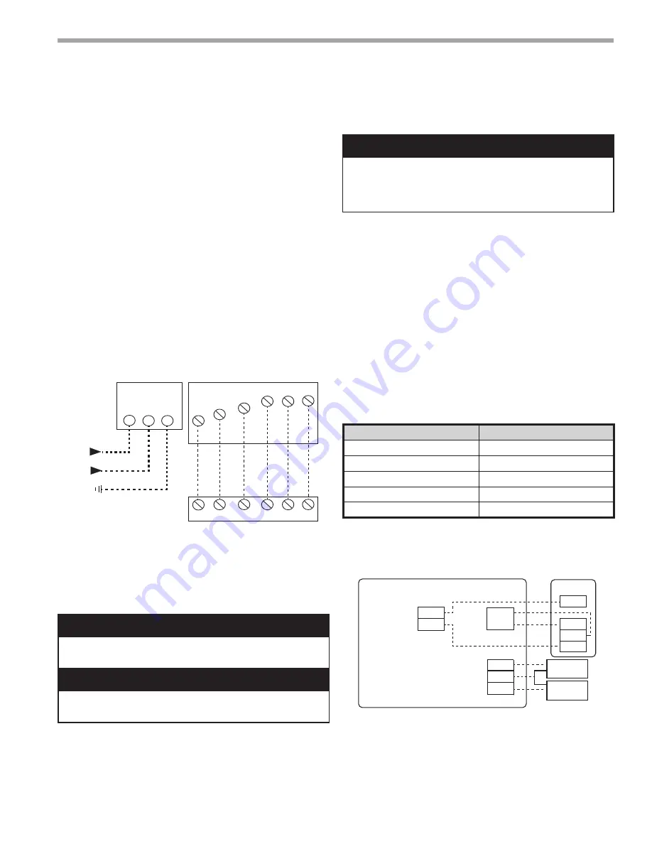
MCO thermostat. A typical field connection diagram is
shown in Figure 14. Refer to instructions provided with
remote thermostat for wiring instructions.
Low-voltage wiring between the unit and the wall
thermostat must comply with all applicable electrical
codes (i.e., NEC and local codes), and be completed before
the unit is installed. Use of eight wire, color-coded, low-
voltage cable is recommended.
Note: Your thermostat may require fewer than
8 connections, 8 wires allow future upgrading
thermostat. Tape off unused wires.
Note: All customer-supplied wiring to be copper only,
and must conform to NEC and local electrical codes.
Wiring shown with dashed lines must be field-supplied
and field-installed.
UNIT
JUNCTION
BOX
L1
L2 GND
R
C
C
G
Y
H
Y2
O
R
G
Y
O
24 Vac
Thermostat
PDB
DXM2
Line
Voltage
Digital 2 Heat, 2 Cool, MCO, or ACO
Will provide auto speed change (for CXM connect Y2 to
blower relay coil - see unit wire diagram).
Table 6: Recommended Thermostat Wire Sizes
WARNING!
Disconnect electrical power source to prevent
injury or death from electrical shock.
CAUTION!
Use copper conductors only to prevent
equipment
damage
Figure 14: Typical Field Connections for units
with Wall-Mounted 24V Thermostat
⚠
WARNING!
⚠
WARNING!
Zone integrity must be maintained to efficiently
control units or groups of units. Unless zones of control are
considered and accounted for, adjacent units may operate in
heating and cooling modes simultaneously.
WIRE SIZE
MAX. WIRE LENGTH
22-Gauge
30 Feet
20-Gauge
50 Feet
18-Gauge
75 Feet
16-Gauge
125 Feet
14-Gauge
200 Feet
*Physical distance from thermostat to unit
⚠
WARNING!
⚠
⚠
CAUTION!
⚠
Figure 14a: Communicating Thermostat to DXM2
Thermostat
Connection to DXM2 Control
Compressor
Compressor Stage 2
Reversing Valve
Fan
24Vac Hot
24Vac Common
Fault LED
DXM2
Board
Y1
Y2
W
H
O
G
R
C
AL1
Y1
Y2
W
DH
O
G
R
C
L
iGate
®
Thermostat
ATC
32
U
03
C
Figure 24a: Communicating Thermostat
24Vac Hot
DXM2
24V
Dehumidification
Notes:
Auxiliary Heat
1) ECM automatic dehumidification mode operates with dehumidification airflows
in the cooling mode when the dehumidification output from thermostat is active.
Normal heating and cooling airflows are not affected.
2) DXM2 board DIP switch S2-7 must be in the auto dehumidification mode for
automatic dehumidification.
3) DH connection not possible with units with internal variable speed pump. Use ATC32U03C.
4) Only use ATC Communicating Thermostat when using Humidifier (H Input) in
units with internal variable speed pump.
Figure 24b: Conventional 3 Heat / 2 Cool Thermostat
Connection to DXM2 Control
Comm +
A+
Comm -
B-
B-
OD
ID
GND
Outdoor
Sensor
(Optional)
Remote Indoor
Sensor
(Optional)
24Vac Common
Gnd
R
C
A+
Unit wiring diagrams available at www.climatemaster.com.
Select ‘Commercial Professional ‘, ‘ Literature ‘,
‘ Wiring Diagrams’


