background image

2- 5  

TEL-14 TWO-CHANNEL TELEPHONE INTERFACE  


RELAY CONTACTS 

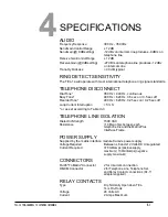
A pair of relay contacts for each line ("A/A1 leads") rated at 2A @ 24 
VAC are available on the DB-9M connector or the RJ-11 adapter. 
This pair of contacts is normally open when the line is "on-hook" 
and closes when the TEL-14 goes "off-

hook.” These contacts are 

not connected to any other circuitry inside the TEL-14 and can be 
used to energize a line-in-use indicator light on a standard multi-line 
phone set, or for any other low-power application. 


SETUP 

AUTOMATIC TELEPHONE LINE NULL 

The TEL-14 features sophisticated automatic nulling circuitry, in addition 
to its integral echo cancellation system. This nulling capability is in two 
parts: 


  The initial telephone line hybrid null is performed the first time a 

telephone line is connected to the TEL-14 or whenever a 
different telephone line is connected. This process is automatic, 
but must be initiated by the user. The way to do this is described 
later in this section and in Chapter 1, 

“Operation.” 

  The continuous dynamic voice null takes place during each 

telephone call. It automatically "fine tunes" the null and cancels 
echoes. 

The TEL-14 must null itself to the telephone line before normal 
operation is optimal. This procedure is to be performed once 
whenever the TEL-14 isconnected to a different telephone line. 
Once this nulling procedure is performed, the TEL-14 will 
remember the telephone line characteristics when it is removed 
from the frame or loses power. It is necessary to null (minimize) the 
sidetone (the sound of the operator's own voice in his or her 
headset) when an external telephone line is placed in an intercom 
environment. Ideally, there should be no portion of the talk signal in 
the listen signal. 


TEL-14'S SIDETONE NULLING PROCEDURE 

Before calling the TEL-14 to automatically null it, connect the external 
telephone line and any other devices that affect the line's impedance. 
These include other telephone extensions connected in parallel on 
the same line. The phone line must be active (turned on at the 
central telephone office) during the nulling process, and all local 
parallel phone sets must be plugged in but on-hook so the line is in 
its normal operating state. 

1.

 Enable the "auto answer" function using the front panel button. 

2.

 Call the TEL-14 interface from a standard telephone set or cellular 

phone. 

Do not 

call the TEL-14 from another TEL-14 in an 

intercom. 

3.

 Press and hold the "auto answer" button for 5 seconds. The 

green "auto answer on" LED will turn off and then turn on again 
after 5 seconds. 

When this happens, release the "auto 

answer" button. 

4.

 Maintain silence on the telephone line. The TEL-14 will listen for 

one second of silence before beginning. The "ring/of- hook" LED 

will then flicker yellow and a series of tones will appear on the 

Summary of Contents for ECLIPSE TEL-14

Page 1: ...CLEAR COM ECLIPSE TEL 14 TWO CHANNEL TELEPHONE INTERFACE I N S T R U C T I O N M A N U A L Part Number 399G278 Rev A 30 November 2018...

Page 2: ...ent may be reproduced in any form by any means without prior written authorization of Clear Com an HME Company This product is covered by U S Patent Nos 8 311 085 and 8 553 865 and by European Patent...

Page 3: ...roduction 2 1 Description 2 2 Wiring 2 3 Setup 2 4 Configuration 2 14 MAINTENANCE 3 1 Introduction 3 1 Troubleshooting 3 1 Block Diagram 3 4 SPECIFICATIONS 4 1 LIMITED WARRANTY 5 I Warranty Period 5 i...

Page 4: ...ratus When a cart is used use caution when moving the cart apparatus combination to avoid injury from tip over 11 Unplug this apparatus during lightning storms or when unused for long periods of time...

Page 5: ...C specifications set out below EN55103 1Electromagnetic compatibility Product family standard for audio video audio visual and entertainment lighting control apparatus for professional use Part 1 Emis...

Page 6: ......

Page 7: ...front panel controls and indicators The option switch settings are described for each mode but they are covered more thoroughly in Chapter 2 The final sections cover the use of the TEL 14 in each of...

Page 8: ...send level LED a send volume control a receive volume control an auto gain adjustable LED an auto gain button an auto gain fixed LED an auto answer LED and an auto answer enable button For more detai...

Page 9: ...lume control sets the level of the signal that the TEL 14 sends to the telephone line by changing the AGC limiting level It is only active when the autogain buttonissetto adjustable The send volume co...

Page 10: ...et to enable This will occur when a TEL 14 is configured in ECS to use Passcodes set up in the System Preferences System Access Codes tab as DTMF Passcodes The use of DTMF passcodes is configured in M...

Page 11: ...llel on the same line The phone line must be active turned on at the central telephone office during the nulling process and all local parallel phone sets must be plugged in but on hook so the line is...

Page 12: ...low station access mode If the immediate manual disconnect feature is disabled there will be a period of 15 seconds between the time when you deactivate the path to the TEL 14 port and the time when t...

Page 13: ...e incoming telephone call available to any station that has the TEL 14 assigned to a key The destination then accesses the call by activating the listen or talk key to the TEL 14 Once the Hook button...

Page 14: ...caller disconnects the TEL 14 line will automatically disconnect after a short time depending upon the response time of the telephone central office Note WhenaTEL 14isconnectedtoanEclipsesystemitwillo...

Page 15: ...modes Intercom station telephone access Self service dial in Manual call screening Intercom to intercom Party line dial in Note Other configurations are possible in addition to the configurations des...

Page 16: ...en the TEL 14 is removed from the frame or powered down Auto answer of incoming calls is a front panel button selection An option switch selects answering each call after 1 or 4 rings The setting of t...

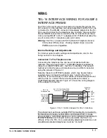
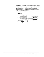
Page 17: ...ne can be accomplished with two methods One is to use the RJ 11 to DB 9M adapters supplied by Clear Com CC 770025 with the TEL 14 interface The second method is to directly wire each telephone line to...

Page 18: ...the telephone when it comes offhook A standard telephone may be installed in series with the TEL 14 by connecting it to pins 1 and 6 of the RJ 11 jack Refer to Figure 2 2 for a diagram showing one wa...

Page 19: ...a different telephone line Once this nulling procedure is performed the TEL 14 will remember the telephone line characteristics when it is removed from the frame or loses power It is necessary to null...

Page 20: ...lephone line Refer to the Option Switch section of this manual for ways to use the TEL 14 options to improve its ability to adapt to poor conditions Note that the null circuits in the TEL 14 are desig...

Page 21: ...HDX Disable Normal Test Mode Spare Ring Count Sense Dial Tone Sense BusyTone Sense Reorder Tone Sense Loop Current Interruption Immediate Manual Disconnect Splash Tones Loop Current Interruption Guar...

Page 22: ...es were connected into the same party line it would be advantageous to set Receive Suppression Disable to the OFF position This prevents noise from one or more telephone lines from interfering with in...

Page 23: ...bled a telephone call can be initiated by any intercom station that has a TEL 14 port label assigned to a selector key Matrix Control enables the station to activate talk paths to the TEL 14 which wil...

Page 24: ...To disable automatic disconnects resulting from reorder tone set option switch S1 4 to OFF The factory default setting is ON providing an automatic disconnect when the TEL 14 senses reorder tone Swit...

Page 25: ...tification Thisswitchwill identifythecard toa Matrix Plus II Matrix Plus 3 or Eclipse Matrix System as a TEL 14 S5 1 and S5 2 should always be operated in concert so that either both are ON or both ar...

Page 26: ...de a call on a TEL 14 line can be answered by any intercom station with a selector key assigned to a TEL 14 port label Intercom stations can originate a call by using the dial phone mode If the call m...

Page 27: ...ls on the telephone line at the end of a call 2 Set the immediate manual disconnect option switch S1 6 to OFF This willpreventcallersfrombeingaccidentallydisconnected iftheyaretransferred from one Mat...

Page 28: ...e factory set ON position This will allow the TEL 14 to disconnect when the call ends 2 Set the Receive Suppression Disable option switch S6 1 to OFF 3 If using revision 11 Matrix Plus 3 intercom soft...

Page 29: ...AC power to thematrix 2 TheTEL 14 will notanswer the telephone line The red Ring Off Hook LED does not light when the line iscalled Check that the telephone line is connected to the TEL 14 As a test...

Page 30: ...ht green when the line is seized Make sure the Matrix Control option Switch S6 6 is set to the ON position Check the Matrix programming to stations which cannot seize the telephone line to make a call...

Page 31: ...itches S6 2 and S6 3 to the OFF position Normally this is not necessary and it will result in an undesirable reduction of trans hybrid loss These switches should only be set to the OFF position if ins...

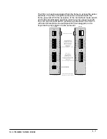
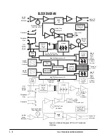
Page 32: ...Controls A Intercom Line B Option Switches CO POTS Line B B Control Line B Front Panel LEDs Switches Volume Controls Telephone Set Contacts Audio From Intercom Figure 3 4 Block Diagram of TEL 14 Telep...

Page 33: ...c off ReorderTone 480 Hz 620 Hz 0 25 sec on 0 25 sec off LoopCurrent Interruption 5 mS or as set according to Table I3 3 TELEPHONE LINE ISOLATION DielectricStrength 1500 VAC Resistance 10 Meg ohms bet...

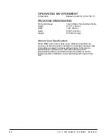
Page 34: ...m Depth 9 5 32 233 mm Weight 0 78 lbs 0 32kg Notice About Specifications While HME Clear Com makes every attempt to maintain the accuracy of the information contained in its product manuals that infor...

Page 35: ...bles accessories components and consumable items have a limited warranty of 90 days Headsets handsets microphones and spare parts have a limited warranty of one year UHF wireless IFB products have a l...

Page 36: ...our equipment You must pay all charges to have the equipment shipped to the support center and returned to you in addition to the costs of the repair EXTENDED WARRANTY You can purchase an extended war...

Page 37: ...g unreasonable or negligent operation abuse accident failure to follow instructions in the manual defective or improperly associated equipment attempts at modification and repair not approved by CLEAR...

Reviews: