2- 2
TEL-14 TWO-CHANNEL TELEPHONE INTERFACE
DESCRIPTION
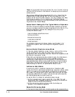
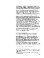
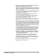
The TEL-14 allows two standard loop start POTS (Plain Old
Telephone Service) lines to connect to ports in the Eclipse matrix.
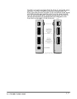
The TEL-14 dual telephone interface is installed in an interface
frame.
The following functions are available for each line:
•
Front panel indication of "ring" and "off-hook" with a single bi-color LED.
•
Front panel mounted manual "hook" switch button for manual
operation of the interface. The "hook" switch function can also
be controlled from the matrix port the line is assigned to.
•
Front panel indication of "send level" with a single bi-color LED.
•
Front panel "send volume" and "receive volume" controls are provided.
•
An "auto gain" button selects whether the automatic gain control
limit is fixed to a normal level or adjustable to other levels. The
setting of this button is retained when the TEL-14 is removed from
the frame or powered down.
•
Auto-answer of incoming calls is a front panel button selection.
An option switch selects answering each call after 1 or 4 rings.
The setting of the front panel button is retained when the TEL-14
is removed from the frame or powered down.
•
Front panel control for commanding automatic renulling of the
telephone line hybrid.
•
Automatic echo suppression DSP.
•
Transformer isolation between the telephone line and intercom.
•
Occupies a single slot in the interface frame.
•
Relay contacts are available to indicate externally an "off-hook"
condition on each line ("A/A1" leads).
INSTALLATION IN AN INTERFACE FRAME
The TEL-14 module can be installed in any available slot in an interface frame.
To install the TEL-14 interface module:
1.
Select a slot to install the interface in.
2.
Remove the blank plate covering the slot.
3.
Set the option switches for the desired mode of operation.
4.
Install the TEL-14 in the slot and make sure the card is fully seated.
5.
Tighten the TEL-14 assembly's front panel mounting screws.
Summary of Contents for ECLIPSE TEL-14
Page 6: ......

