32
STEP 2: INSTALLING THE CONTROL HORN
❑
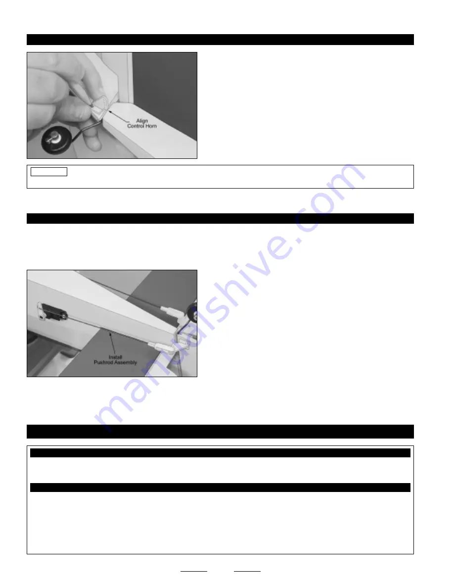
Position the nylon control horn onto one right side of the rudder.
When aligned properly, the centerline of the control horn should be 3/8"
up from the bottom of the rudder (at the hinge line) and the clevis
attachment holes should be lined up over the hinge line. The base of
the control horn should be angled up slightly, too, so that the control
horn will line up better with the pushrod wire.
❑
When satisfied with the alignment, mark and drill 5/64" diameter
pilot holes through the rudder for the control horn mounting screws.
Before installing the control horn in the next procedure, drip several drops of thin C/A into the pilot holes and allow
the C/A to fully cure. The C/A will harden the surrounding balsa, making the mounting area stronger.
❑
Install the control horn and backplate, using two M2 x 12mm machine screws, being careful not to overtighten them.
PRO TIP
❑
Install the servo horn, pushrod wire and nylon clevis, using the same
techniques as you used to install the elevator servo horn, pushrod wire
and nylon clevis.
☞
Like with the elevator pushrod assembly, the Z-Bend in the rudder
pushrod wire should be 9/16" out from the center of the servo arm, and
the nylon clevis should be installed in the outermost hole in the control
horn. The servo horn should point down toward the bottom of the
fuselage, too.
❑
Move the rudder right and left several times to ensure that the pushrod assembly does not bind. It should operate smoothly in
both directions.
STEP 3: INSTALLING THE PUSHROD ASSEMBLY
❑
Connect your radio system and plug the rudder servo into the receiver. Center the servo by double-checking that the rudder
trim lever on your transmitter is centered.
❑
Use a couple of pieces of masking tape, taped between the rudder and the fuselage, to hold the rudder centered.
❑
Kwik Bond 5 Minute Epoxy
❑
# 1 Phillips Head Screwdriver
❑
Needle Nose Pliers
❑
Excel Modeling Knife
❑
Electric Drill
❑
1/16" Drill Bit
❑
Ruler
❑
Pencil
❑
Masking Tape
❑
NHP Epoxy Mixing Sticks
❑
NHP Epoxy Mixing Cups
YOU'LL NEED THE FOLLOWING PARTS FROM THE KIT:
YOU'LL NEED THE FOLLOWING TOOLS AND SUPPLIES:
SECTION 17: AILERON CONTROL SYSTEM INSTALLATION
❑
(2) 3-3/8" Threaded Wires w/Z-Bends
❑
(2) Nylon Control Horns
❑
(2) Nylon Clevises
❑
(4) M2 x 10mm Wood Screws
Continued On Next Page
☛
☛
☛
☛
☛


