Chapter 2 Operating Principles
2-1.
Operation of Each Mechanism
2-7
CL-E700 series
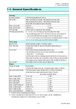
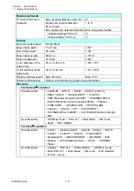
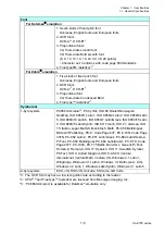
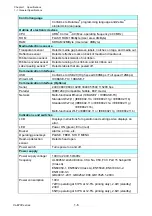
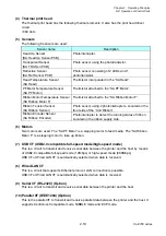
2-1-2. Media Feed/Printing Mechanism
The major components of the media feed/printing mechanism are:
(a) SA Head
(b) SA PF Motor
(c) SA Platen
(d) Gear train
By setting the head block to the down position, the media is pushed against the “SA Platen” by the
“SA Head”.
As the “SA PF Motor” (stepping motor) turns counterclockwise viewing from the right side of the
printer, the “SA Platen” turns counterclockwise via the gear train (“Gear PF1”, “Gear PF2” and
“Gear PF Idle”) and the media is fed forward by a friction force produced between the “SA Platen”
and the “SA Head”.
In the direct thermal printing, thermal paper is heated by the energized thermal elements of the “SA
Head” and printing is done.
While in the thermal transfer printing using ink ribbon, ink on the ribbon is melted by the energized
thermal elements of the “SA Head” and transferred on the media surface.
When the “SA PF Motor” turns clockwise, the media is fed backwards
.
[Right side view]
SA Head
1
2
3
4
5
6
Thermal Elements
SA PF Motor
SA Platen
Gear PF Idle
Gear PF2
Motor Gear
Gear PF1
Ribbon
Media
Summary of Contents for CL-E700 Series
Page 1: ...Technical Manual CL E700 series Thermal Transfer Printer...
Page 5: ...Chapter 1 Specifications 1 1 CL E700 series CHAPTER 1 SPECIFICATIONS...
Page 15: ...Chapter 2 Operating Principles 2 1 CL E700 series CHAPTER 2 OPERATING PRINCIPLES...
Page 87: ...Chapter 3 Disassembly and Maintenance 3 1 CL E700 series CHAPTER 3 DISASSEMBLY AND MAINTENANCE...
Page 151: ...Chapter 4 Troubleshooting 4 1 CL E700 series CHAPTER 4 TROUBLESHOOTING...
Page 167: ...Chapter 5 Parts Lists CL E700 series CHAPTER 5 PARTS LISTS...
Page 172: ...Chapter 5 Parts Lists CL E700 series 5 6 DRAWING NO 1 General Assembly Rev 0...
Page 195: ...Chapter 5 Parts Lists 5 29 CL E700 series DRAWING NO 7 Unit Opepane Rev 0...
Page 203: ...Chapter 5 Parts Lists 5 37 CL E700 series DRAWING NO 9 SA2 Ribbon Unit Fan Rev 0...
Page 206: ...Chapter 5 Parts Lists CL E700 series 5 40 DRAWING NO 10 Accessories Rev 0 3 2 4 1 1 1 2 1 3...
Page 208: ...Chapter 6 Circuit Diagrams 6 1 CL E700 series CHAPTER 6 CIRCUIT DIAGRAMS...
Page 230: ...Appendices AP 1 CL E700 series APPENDICES...
Page 233: ...Appendices A Mounting Diagrams CL E700 series AP 4 2 Solder side...

