Chapter 2 Operating Principles
2-4. Interface
2-67
CL-E700 series
2-4-3. Serial Interface (Option)
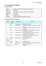
(1)
Specifications
System
Start/stop asynchronous full duplex communication
Signal level
RS-232C
Baud rate
2400, 4800, 9600, 19200, 38400, 57600, 115200 bps
Data length
7 bits, 8 bits
Stop bit
1 bit, 2 bits
Parity Odd,
even,
none
Connector
D-SUB 225AE25FGTBBA3 25-pin (COXOC)
(2)
Signal line and pin assignment
Pin No.
Signal
Abbr.
Signal name
Function
1
FG
Frame ground
Protective grounding
2
TXD
Transmit Data
Signal line that transmits data from the printer to
the host
3
RXD
Receive data
Signal line that transmits data from the host to
the printer
4
RTS
Request To Send Signal line that is active when the printer can
receive data from the host
5
CTS
Clear To Send
Signal line that is active when the host can
receive data from the printer
6
DSR
Data Set Ready
Signal line that is active when the host can
interface with the printer
7
SGND
Signal ground
Signal grounding line
8-13,
15-19
NC -
Not
used
14
VCC
+5V
(Factory use only )
20 DTR
Data
Terminal
Ready
Signal line that is active when the printer can
interface with the host
21-25 NC
-
Not
used
Summary of Contents for CL-E700 Series
Page 1: ...Technical Manual CL E700 series Thermal Transfer Printer...
Page 5: ...Chapter 1 Specifications 1 1 CL E700 series CHAPTER 1 SPECIFICATIONS...
Page 15: ...Chapter 2 Operating Principles 2 1 CL E700 series CHAPTER 2 OPERATING PRINCIPLES...
Page 87: ...Chapter 3 Disassembly and Maintenance 3 1 CL E700 series CHAPTER 3 DISASSEMBLY AND MAINTENANCE...
Page 151: ...Chapter 4 Troubleshooting 4 1 CL E700 series CHAPTER 4 TROUBLESHOOTING...
Page 167: ...Chapter 5 Parts Lists CL E700 series CHAPTER 5 PARTS LISTS...
Page 172: ...Chapter 5 Parts Lists CL E700 series 5 6 DRAWING NO 1 General Assembly Rev 0...
Page 195: ...Chapter 5 Parts Lists 5 29 CL E700 series DRAWING NO 7 Unit Opepane Rev 0...
Page 203: ...Chapter 5 Parts Lists 5 37 CL E700 series DRAWING NO 9 SA2 Ribbon Unit Fan Rev 0...
Page 206: ...Chapter 5 Parts Lists CL E700 series 5 40 DRAWING NO 10 Accessories Rev 0 3 2 4 1 1 1 2 1 3...
Page 208: ...Chapter 6 Circuit Diagrams 6 1 CL E700 series CHAPTER 6 CIRCUIT DIAGRAMS...
Page 230: ...Appendices AP 1 CL E700 series APPENDICES...
Page 233: ...Appendices A Mounting Diagrams CL E700 series AP 4 2 Solder side...

