Chapter 3 Disassembly and Maintenance
3-6. Disassembly, Reassembly and Lubrication
3-
29
CL-E700
series
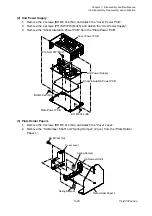
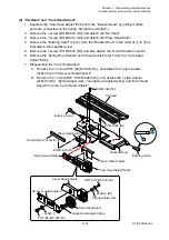
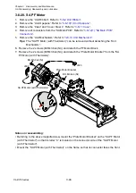
(2) Unit Power Supply
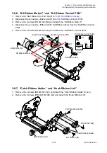
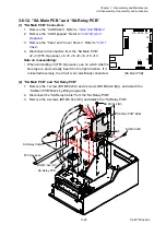
1. Remove the 2 screws (BH M3.0x4 (NI)) and detach the “Cover Power PCB”.
2. Remove the 4 screws (PH (SW+PW) M3x5) and detach the “Unit Power Supply”.
3. Remove the “Sheet Insulation Power PCB” from the “Plate Power PCB”.
(3) Plate Holder Paper L
1. Remove the 3 screws (BH M3.0x4 (NI)) and detach the “Cover Lever”.
2. Remove the “SA Damper Shaft” and “Spring Damper” (2 pcs.) from the “Plate Holder
Paper L”.
Plate Holder Paper L
SA Damper Shaft
Cover Lever
Spring Damper
Spring Damper
BH M3.0x4 (NI)
Cover Power PCB
Plate Power PCB
Sheet Insulation Power PCB
PH (SW+PW) M3x5
Unit Power Supply
BH M3.0x4 (NI)
BH M3.0x4 (NI)
Summary of Contents for CL-E700 Series
Page 1: ...Technical Manual CL E700 series Thermal Transfer Printer...
Page 5: ...Chapter 1 Specifications 1 1 CL E700 series CHAPTER 1 SPECIFICATIONS...
Page 15: ...Chapter 2 Operating Principles 2 1 CL E700 series CHAPTER 2 OPERATING PRINCIPLES...
Page 87: ...Chapter 3 Disassembly and Maintenance 3 1 CL E700 series CHAPTER 3 DISASSEMBLY AND MAINTENANCE...
Page 151: ...Chapter 4 Troubleshooting 4 1 CL E700 series CHAPTER 4 TROUBLESHOOTING...
Page 167: ...Chapter 5 Parts Lists CL E700 series CHAPTER 5 PARTS LISTS...
Page 172: ...Chapter 5 Parts Lists CL E700 series 5 6 DRAWING NO 1 General Assembly Rev 0...
Page 195: ...Chapter 5 Parts Lists 5 29 CL E700 series DRAWING NO 7 Unit Opepane Rev 0...
Page 203: ...Chapter 5 Parts Lists 5 37 CL E700 series DRAWING NO 9 SA2 Ribbon Unit Fan Rev 0...
Page 206: ...Chapter 5 Parts Lists CL E700 series 5 40 DRAWING NO 10 Accessories Rev 0 3 2 4 1 1 1 2 1 3...
Page 208: ...Chapter 6 Circuit Diagrams 6 1 CL E700 series CHAPTER 6 CIRCUIT DIAGRAMS...
Page 230: ...Appendices AP 1 CL E700 series APPENDICES...
Page 233: ...Appendices A Mounting Diagrams CL E700 series AP 4 2 Solder side...

