Chapter 2 Operating Principles
2-2.
Operation of Control Parts
2-25
CL-E700 series
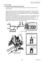
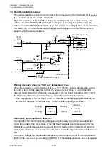
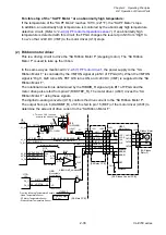
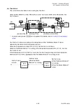
When the transparent sensor is conducted, the voltage at pin 96 (SNSTRA) varies depending
on the characteristics of the light receiving element (phototransistor) of the transparent sensor
and other factors. To solve this problem, the FPGA (U5) outputs SNSCTL0 (pin N9) and
SNSCTL1 (pin N11) signals to turn ON or OFF Q11 and Q10. Thus, R102 and R101 (voltage
dividing resistors) are connected or disconnected to minimize the difference in level at pin 96
(SNSTRA).
The current flowing into the LEDs is determined by the data sent from the FPGA to the
digital-to-analog converter (U16). The digital-to-analog converter converts the data received
from the FPGA and outputs resoultant level at pin 3. The base current of the transistor Q7 is
determined by this level. This means that the current flowing into the LEDs is also determined
by this level. In the actual control, the FPGA changes data (LED current) to keep the level at
pin 96 (SNSTRA) of the CPU constant.
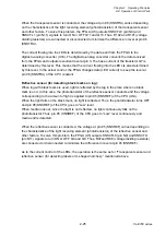
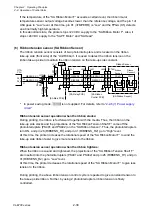
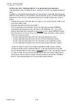
Reflective sensor (for detecting black marks on tag):
When tag with black marks is used, light is reflected by the tag in the place where no black
mark is on it. In this case, the phototransistor of the reflective sensor conducts and the voltage
corresponding to the amount of light is applied to pin 95 (SNSREF) of the CPU (U1A).
When the light falls on the black mark, no light is reflected. Thus, the phototransistor turns OFF
and pin 95 (SNSREF) of the CPU goes to “Low” level.
When media runs out, since the light is not reflected, no light continuously falls on the
phototransistor. Thus, pin 95 (SNSREF) of the CPU goes to “Low” level continuously and
media end is detected.
When the reflective sensor is conducted, the voltage at pin 95 (SNSREF) varies depending on
the characteristics of the light receiving element (phototransistor) of the reflective sensor and
other factors. To solve this problem, the FPGA (U5) outputs SNSCTL0 (pin N9) and SNSCTL1
(pin N11) signals to turn ON or OFF Q9 and Q8. Thus, R97and R96 (voltage dividing resistors)
are connected or disconnected to minimize the difference in level at pin 95 (SNSREF).
As to the current control of the LEDs, the operation is the same as for “Transparent sensor and
reflective sensor (for detecting labels or U-shaped notches):” mentioned above.
Summary of Contents for CL-E700 Series
Page 1: ...Technical Manual CL E700 series Thermal Transfer Printer...
Page 5: ...Chapter 1 Specifications 1 1 CL E700 series CHAPTER 1 SPECIFICATIONS...
Page 15: ...Chapter 2 Operating Principles 2 1 CL E700 series CHAPTER 2 OPERATING PRINCIPLES...
Page 87: ...Chapter 3 Disassembly and Maintenance 3 1 CL E700 series CHAPTER 3 DISASSEMBLY AND MAINTENANCE...
Page 151: ...Chapter 4 Troubleshooting 4 1 CL E700 series CHAPTER 4 TROUBLESHOOTING...
Page 167: ...Chapter 5 Parts Lists CL E700 series CHAPTER 5 PARTS LISTS...
Page 172: ...Chapter 5 Parts Lists CL E700 series 5 6 DRAWING NO 1 General Assembly Rev 0...
Page 195: ...Chapter 5 Parts Lists 5 29 CL E700 series DRAWING NO 7 Unit Opepane Rev 0...
Page 203: ...Chapter 5 Parts Lists 5 37 CL E700 series DRAWING NO 9 SA2 Ribbon Unit Fan Rev 0...
Page 206: ...Chapter 5 Parts Lists CL E700 series 5 40 DRAWING NO 10 Accessories Rev 0 3 2 4 1 1 1 2 1 3...
Page 208: ...Chapter 6 Circuit Diagrams 6 1 CL E700 series CHAPTER 6 CIRCUIT DIAGRAMS...
Page 230: ...Appendices AP 1 CL E700 series APPENDICES...
Page 233: ...Appendices A Mounting Diagrams CL E700 series AP 4 2 Solder side...

