background image

3-2

Cisco MWR 1941-DC Mobile Wireless Edge Router Software Configuration Guide

OL-11503-01

Chapter 3      First-Time Configuration

    Before You Begin

Understanding MWR 1941-DC Router Interface Numbering

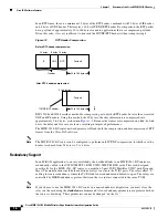
Each network interface on a Cisco MWR 1941-DC router is identified by a slot number and a port 
number.

Figure 3-1

 shows an example of interface numbering on a Cisco MWR 1941-DC router with the 

following configuration for a Cell Site DCN implementation:

A VWIC in three of the three VWIC slots

A 4-port asynchronous/synchronous serial network module in slot 1

Two built-in Fast Ethernet interfaces

Figure 3-1

Cisco MWR 1941-DC Router Port Numbers

Slot and Port Numbering

The Cisco MWR 1941-DC router chassis contains the following LAN and WAN interface types: 

Two built-in Fast Ethernet LAN interfaces

Three slots in which you can install Voice/WAN interface cards (VWICs) 

One slot in which you can install a network module

The slot numbers are as follows:

0 for all built-in interfaces

0 for all built-in VWIC slots

1 for the network module slot

The numbering format is:

Interface type Slot number/Interface number

98716

SEE MANUAL

 BEFORE IN

STALLATION

DSU

56K

SEE MANUAL

 BEFORE IN

STALLATION

DSU

56K

CONSOLE

AUXILIARY

CN/LP

2

1

0

3

RXC

RXD

TXC

TXD

CN/LP

RXC

RXD

TXC

TXD

CN/LP

RXC

RXD

TXC

TXD

CN/LP

RXC RXD

TXC

TXD

EN

SERIAL
A/S

Serial 0/3

Serial 0/2

Serial 0/1

Serial 0/0

Serial 1/3

Serial 1/2

Serial 1/1

Serial 1/0

FE1

FE0

Console

port

Auxiliary

port

Summary of Contents for MWR 1941-DC - 1941 Mobile Wireless Router

Page 1: ...c 170 West Tasman Drive San Jose CA 95134 1706 USA http www cisco com Tel 408 526 4000 800 553 NETS 6387 Fax 408 526 4100 Cisco MWR 1941 DC Mobile Wireless Edge Router Software Configuration Guide October 27 2006 Text Part Number OL 11503 01 ...

Page 2: ...erference by using one or more of the following measures Turn the television or radio antenna until the interference stops Move the equipment to one side or the other of the television or radio Move the equipment farther away from the television or radio Plug the equipment into an outlet that is on a different circuit from the television or radio That is make certain the equipment and the televisi...

Page 3: ...oblems in Cisco Products xiv Product Alerts and Field Notices xv Obtaining Technical Assistance xv Cisco Technical Support Documentation Website xv Submitting a Service Request xvi Definitions of Service Request Severity xvii Obtaining Additional Publications and Information xvii C H A P T E R 1 Overview of the Cisco MWR 1941 DC Router 1 1 Primary Uses of the MWR 1941 DC Router 1 1 IP RAN Solution...

Page 4: ...rstanding Command Modes 2 2 Undoing a Command or Feature 2 3 Saving Configuration Changes 2 3 Where to Go Next 2 3 C H A P T E R 3 First Time Configuration 3 1 Before You Begin 3 1 Understanding Boot Images 3 1 Understanding MWR 1941 DC Router Interface Numbering 3 2 Slot and Port Numbering 3 2 Before Starting Your Router 3 3 Using the Setup Command Facility 3 3 Configuring Global Parameters 3 4 C...

Page 5: ...eed and Duplex Mode 4 5 Configuring Routing Protocol Attributes 4 6 Configuring PIM 4 6 Configuring HSRP Support 4 6 Enabling the FE Interface 4 8 Configuring Multilink Interfaces 4 8 Configuring Multilink PPP 4 9 Configuring IP Address Assignment 4 9 Configuring PPP Multiplexing 4 10 Configuring ACFC and PFC Handling During PPP Negotiation 4 11 Configuring RTP UDP Compression 4 12 Configuring the...

Page 6: ... R 6 Configuring the MWR 1941 DC in a Cell Site DCN 6 1 Before You Begin 6 2 Verifying the Version of Cisco IOS Software 6 3 Configuring the Host Name and Password 6 3 Verifying the Host Name and Password 6 5 Configuring Fast Ethernet Interfaces 6 5 Configuration Example 6 6 Configuring the Ethernet Switch Network Module 6 6 Configuration Example 6 6 Configuring Asynchronous Synchronous Serial Net...

Page 7: ...s 6 26 Configuring the AIC 6 26 Accessing the AIC 6 29 Configuring the NOC IP Address 6 30 Configuring Alarms 6 30 Programming the Analog Contact Points 6 31 Programming the Discrete Contact Points 6 32 Verifying the IP Address 6 33 Troubleshooting Tips 6 35 Monitoring and Maintaining the NM AIC 64 Contact Closure Network Module 6 35 Software Upgrade 6 35 Configuration Backup 6 35 Override 6 36 Co...

Page 8: ...g Access to a Line or Interface 6 59 Controlling Policy Routing and the Filtering of Routing Information 6 59 Controlling Dialer Functions 6 59 Configuration Examples 6 60 Numbered Access List Examples 6 60 Named Access List Example 6 62 IP Extended Access List with Fragment Control Example 6 62 Time Range Applied to an IP Access List Example 6 62 Commented IP Access List Entry Examples 6 63 Savin...

Page 9: ...lowing sections Document Revision History page x Objectives page x Audience page x Organization page x Document Conventions page xi Additional Information page xii Related Documentation page xii Obtaining Documentation page xiii Documentation Feedback page xiv Cisco Product Security Overview page xiv Product Alerts and Field Notices page xv Obtaining Technical Assistance page xv Obtaining Addition...

Page 10: ...administrators who are familiar with the fundamentals of router based internetworking but who might not be familiar with Cisco IOS software System administrators who are responsible for installing and configuring internetworking equipment and who are familiar with Cisco IOS software Organization The major sections of this software configuration guide include Revision Date Change Summary OL 11503 0...

Page 11: ...OS software command line interface CLI to configure basic router functionality in an IP RAN Chapter 5 Cisco MWR 1941 DC Router IP RAN Command Reference Provides information about new and changed commands Chapter 6 Configuring the MWR 1941 DC in a Cell Site DCN Describes how to use the Cisco IOS software command line interface CLI to configure basic router functionality in Cell Site DCN Chapter Tit...

Page 12: ...on The following list includes documentation related to your product by implementation Cisco Mobile Wireless IP RAN http www cisco com univercd cc td doc product wireless ipran 1_0 index htm Cisco MWR 1941 Mobile Wireless Edge Router Documents Cisco MWR 1941 DC Mobile Wireless Edge Router Hardware Installation Guide Cisco MWR 1941 DC Mobile Wireless Edge Router Rack Mounting Instructions Regulator...

Page 13: ...com You can access the most current Cisco documentation at this URL http www cisco com techsupport You can access the Cisco website at this URL http www cisco com You can access international Cisco websites at this URL http www cisco com public countries_languages shtml Product Documentation DVD The Product Documentation DVD is a library of technical product documentation on a portable medium The ...

Page 14: ...ain assistance with security incidents that involve Cisco products Register to receive security information from Cisco A current list of security advisories security notices and security responses for Cisco products is available at this URL http www cisco com go psirt To see security advisories security notices and security responses as they are updated in real time you can subscribe to the Produc...

Page 15: ...Product Alerts and Cisco Field Notices You can receive Cisco Product Alerts and Cisco Field Notices by using the Product Alert Tool on Cisco com This tool enables you to create a profile and choose those products for which you want to receive information To access the Product Alert Tool you must be a registered Cisco com user To register as a Cisco com user go to this URL http tools cisco com RPF ...

Page 16: ...nformation narrow your search to look in technical documentation not the entire Cisco com website On the Cisco com home page click the Advanced Search link under the Search box and then click the Technical Support Documentation radio button To provide feedback about the Cisco com website or a particular technical document click Contacts Feedback at the top of any Cisco com web page Submitting a Se...

Page 17: ...ere you can sign up for a variety of Cisco e mail newsletters and other communications Create a profile and then select the subscriptions that you would like to receive To visit the Cisco Online Subscription Center go to this URL http www cisco com offer subscribe The Cisco Product Quick Reference Guide is a handy compact reference tool that includes brief product overviews key features sample par...

Page 18: ...this URL http www cisco com discuss networking What s New in Cisco Documentation is an online publication that provides information about the latest documentation releases for Cisco products Updated monthly this online publication is organized by product category to direct you quickly to the documentation for your products You can view the latest release of What s New in Cisco Documentation at thi...

Page 19: ...e MWR 1941 DC Router page 1 1 Cisco IOS Software Features page 1 4 Limitations and Restrictions page 1 9 Primary Uses of the MWR 1941 DC Router The MWR 1941 DC router is designed to be used at the cell site as part of an IP RAN or Cell Site DCN solution IP RAN Solution Note Cisco IOS Release 12 3 11 T supports the Cisco IOS IP RAN feature set software image for the MWR 1941 DC router In an IP RAN ...

Page 20: ...2MFT E1 DIR in each router to ensure that the relays on the active router are closed and the relays on the standby router are open to avoid double termination of the T1 or E1 Cell Site DCN Solution Note Cisco IOS Release 12 3 11 T does not support the Cisco IOS Cell Site DCN feature set software image for the MWR 1941 DC router In a Cell Site DCN the MWR 1941 DC router can be used to extend a mobi...

Page 21: ...es a channelized T1 E1 interface to the BTS and routes management and control traffic via one DS0 from a T1 Additionally the MWR 1941 DC router supports a variety of interfaces to monitored and controlled devices using Cisco network modules installed in the MWR 1941 DC router Network Operations Center BTS Node B DCN traffic 10 100 Base T T1 E1 MWR 1941 DC 7200 1 0 DACS BSC RNC Voice circuits T1 E1...

Page 22: ... known as Parallel eXpress Forwarding PXF When deployed in an IP RAN the MWR 1941 DC router is customized for performance high availability quality of service and link efficiency Cisco IOS software functions added to the MWR 1941 DC router for the IP RAN implementation include Redundancy logic For monitoring Hot Standby Routing Protocol HSRP information to determine the active and standby router a...

Page 23: ...as Forwarding Drop and Interface IPv4 MLPPP MLP PPP Data Path MLP LFI is not supported PPPmux cRTP cUDP Link Noise Monitoring LNM provides configuration monitoring of individual T1 E1 circuit quality PPP Multiplexing Demultiplexing Encapsulated PPP frames contain several bytes of header information which adds overhead to a network that is used to transport PPP frames RFC 3153 describes a way to ov...

Page 24: ...ression of RTP frames from the Cisco IOS software Note The MWR 1941 DC router can be configured to perform only IP UDP compression in which case the header is reduced from 28 bytes to 2 to 4 bytes Redundancy Support In an IP RAN application to ensure availability the backhaul links to an MWR 1941 DC router are redundantly cabled to the VWIC 2MFT T1 DIR VWIC 2MFT E1 DIR cards This card designed spe...

Page 25: ...to the MGX RPM 1FE CP back card Ignore IP ID Field Delta in cUDP Packet Flows With Cisco IOS Release 12 2 8 MC2c and later by default the ability to ignore IP ID field delta in cUDP traffic flows is enabled This ability eliminates the need to send information about the IP header ID field in compressed packets The decompressor saves the original ID field from the full header packet and generates an...

Page 26: ...lementing the MWR 1941 DC router in a Cell Site DCN runs on the MIPs based router processor portion of the MWR 1914 DC router hardware Standard Cisco IOS software features supported in the MWR 1914 DC router for the Cell Site DCN implementation include Standard and extended Access Control Lists IP Fragmentation IP Multicast IGMP MLPPP PPPo HDLC HSRP OSPF DHCP IP Precedence cRTP cUDP CB WFQ Traffic...

Page 27: ... powered up router might cause damage to the card Caution Removing the compact flash from the Cisco MWR 1941 DC router during a read write operation might corrupt the contents of the compact flash rendering it useless To recover from an accidental removal of or corruption to the compact flash a maintenance spare with the appropriate bootable Cisco IOS software image might be needed CISCO ACCESS EN...

Page 28: ...upported WIC is the VWIC 2MFT T1DIR VWIC 2MFT E1DIR IP RAN implementation only Upgrading the VWIC 2MFT T1 DIR Microcode When upgrading the image on your Cisco MWR 1941 DC router power cycle the router or perform a microcode reload on the VWIC 2MFT T1 DIR to ensure that the firmware for the VWIC 2MFT T1 DIR is updated during the upgrade Disabling PPP Multiplexing To fully disable PPP multiplexing P...

Page 29: ...icrocode reload on the VWIC 2MFT T1 DIR to ensure that the firmware for the VWIC 2MFT T1 DIR is updated during the upgrade New Features in Cisco IOS Release 12 2 15 MC2h The following new features are implemented in Cisco IOS Release 12 2 15 MC2h and later releases Support for 6 T1 E1 interfaces per MWR Support for 1800 Context IDs CIDs per MWR Support for enhanced Link Noise Monitoring LNM Suppor...

Page 30: ...rage noise at any time represents the noise average for the last configured duration in seconds It is recalculated each second as the noise samples arrive each second Basically it s a sliding window of noise averages for the last duration in seconds The Benefits of this new algorithm are the following Improves CDMA backhaul link robustness by detecting noisy spans and removing them out of service ...

Page 31: ...LI If you have never used the Cisco IOS software or need a refresher take a few minutes to read this chapter before you proceed to the next chapter If you are already familiar with the Cisco IOS software proceed to Part 2 Implementing the MWR 1941 DC Router in an IP RAN Getting Help Use the question mark and arrow keys to help you enter commands For a list of available commands enter a question ma...

Page 32: ...ure terminal Router config interface serial 0 0 Router config if line 0 Router config line controller t1 0 Router config controller exit Router config exit Router SYS 5 CONFIG_I Configured from console by console The last message is normal and does not indicate an error Press Return to get the Router prompt Note You can press Ctrl z in any mode to immediately return to enable mode Router instead o...

Page 33: ... save the configuration to NVRAM After the configuration has been saved the following appears OK Router Where to Go Next Now that you have learned some Cisco IOS software basics you can begin to configure the router using the CLI Remember that You can use the question mark and arrow keys to help you enter commands Each command mode restricts you to a set of commands If you have difficulty entering...

Page 34: ...2 4 Cisco MWR 1941 DC Mobile Wireless Edge Router Software Configuration Guide OL 11503 01 Chapter 2 Cisco IOS Software Basics Where to Go Next ...

Page 35: ...he router manually or you wish to configure a module or interface that is not included in the setup command facility proceed to Chapter 2 Cisco IOS Software Basics to familiarize yourself with the command line interface CLI and then proceed to PART II for instructions on configuring your MWR 1941 DC router Before You Begin This section contains information with which you should be familiar before ...

Page 36: ... Router Port Numbers Slot and Port Numbering The Cisco MWR 1941 DC router chassis contains the following LAN and WAN interface types Two built in Fast Ethernet LAN interfaces Three slots in which you can install Voice WAN interface cards VWICs One slot in which you can install a network module The slot numbers are as follows 0 for all built in interfaces 0 for all built in VWIC slots 1 for the net...

Page 37: ...eate a new configuration for the interfaces that you previously configured on W1 which will now be Serial 0 2 and Serial 0 3 The slot number of WIC VWIC interfaces installed in slot 1 using a WAN network module is always 1 and the interfaces are always numbered from the right to left The slot number for all network module interfaces is always 1 and the interfaces are always numbered from right to ...

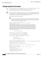
Page 38: ...0 i mz 12042001 program load complete entry point 0x80008000 size 0x658258 Self decompressing the image OK Restricted Rights Legend Use duplication or disclosure by the Government is subject to restrictions as set forth in subparagraph c of the Commercial Computer Software Restricted Rights clause at FAR sec 52 227 19 and subparagraph c 1 ii of the Rights in Technical Data and Computer Software cl...

Page 39: ...to privileged EXEC and configuration modes This password after entered becomes encrypted in the configuration Enter enable secret xxxx Step 5 Enter an enable password that is different from the enable secret password This password is not encrypted less secure and can be seen when viewing the configuration The enable password is used when you do not specify an enable secret password with some older...

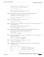
Page 40: ...ples of the setup steps for each interface module Refer to the sections appropriate to your router s configuration Configuration for network modules includes Ethernet Interface Configuration page 3 6 FastEthernet Interface Configuration page 3 7 Serial Interface Configuration page 3 7 Asynchronous Synchronous Serial Interface Configuration page 3 10 When you complete the setup steps for your inter...

Page 41: ...the values appropriate for your router and network The messages you see may vary Do you want to configure Serial0 0 interface yes Some encapsulations supported are ppp hdlc frame relay lapb atm dxi smds x25 Choose encapsulation type ppp Note The following sections describe the prompts for each encapsulation type For PPP and HDLC encapsulation no further configuration is needed No serial cable seen...

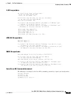
Page 42: ... IP address for the remote interface 2 0 0 2 Do you want to map a remote machine s IPX address to dlci yes IPX address for the remote interface 40 1234 5678 Serial interface needs clock rate to be set in dce mode The following clock rates are supported on the serial interface 0 1200 2400 4800 9600 19200 38400 56000 64000 72000 125000 148000 500000 800000 1000000 1300000 2000000 4000000 8000000 cho...

Page 43: ...128 ATM DXI Encapsulation Enter VPI number 1 Enter VCI number 1 Do you want to map the remote machine s IP address to vpi and vci s yes IP address for the remote interface 2 0 0 2 Do you want to map the remote machine s IPX address to vpi and vci s yes IPX address for the remote interface 40 1234 5678 SMDS Encapsulation Enter smds address for the local interface c141 5556 1415 We will need to map ...

Page 44: ... plugged in to your router you need to indicate whether the interface is to be used as DTE or DCE If a cable is present the setup command facility determines the DTE DCE status If the serial cable is DCE you see the following prompt Configure IP on this interface no yes Configure IP unnumbered on this interface no IP address for this interface 2 0 0 0 Subnet mask for this interface 255 0 0 0 Class...

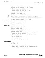
Page 45: ...Encapsulation lapb circuit can be either in dce dte mode Choose either from dce dte dte X 25 Encapsulation x25 circuit can be either in dce dte mode Choose from either dce dte dte Enter local x25 address 1234 We will need to map the remote x 25 station s x25 address to the remote stations IP IPX address Enter remote x25 address 4321 Do you want to map the remote machine s x25 address to IP address...

Page 46: ... IP on this interface yes Configure IP unnumbered on this interface no IP address for this interface 2 0 0 0 Subnet mask for this interface 255 0 0 0 Class A network is 2 0 0 0 0 subnet bits mask is 8 Configure LAT on this interface no Configure AppleTalk on this interface no Configure DECnet on this interface no Configure CLNS on this interface no Configure IPX on this interface no yes IPX networ...

Page 47: ...re now at the command line interface CLI and you have just completed a basic router configuration However this is not a complete configuration You must configure additional parameters using the Cisco IOS software CLI as described in Part 2 Implementing the MWR 1941 DC Router in an IP RAN Where to Go Next At this point you can proceed to the following Part 2 Implementing the MWR 1941 DC Router in a...

Page 48: ...3 14 Cisco MWR 1941 DC Mobile Wireless Edge Router Software Configuration Guide OL 11503 01 Chapter 3 First Time Configuration Where to Go Next ...

Page 49: ...P A R T 1 Implementing the MWR 1941 DC Router in an IP RAN ...

Page 50: ......

Page 51: ...Monitor page 4 21 Saving Configuration Changes page 4 24 Verifying the Configuration page 4 24 Monitoring and Managing the MWR 1941 DC page 4 28 Where to Go Next page 4 30 Follow the procedures in this chapter to configure the router manually or if you want to change the configuration after you have run the setup command facility described in Chapter 1 First Time Configuration This chapter describ...

Page 52: ... the IP addresses of the E1 T1 interfaces of the standby router Verifying the Version of Cisco IOS Software To implement the MWR 1941 DC router in an IP RAN Cisco IOS Release 12 2 8 MC2 or a later must be installed on the router To verify the version of Cisco IOS software use the show version command The show version command displays the configuration of the system hardware the software version th...

Page 53: ...n0 is now available Press RETURN to get started Router enable Password guessme Router Step 4 Router config enable secret guessme Enter an enable secret password This password provides access to privileged EXEC mode When a user types enable at the EXEC prompt Router they must enter the enable secret password to gain access to configuration mode Substitute your enable secret for guessme Step 5 Route...

Page 54: ...d revertive interfaces The health interface monitors the status of the redundant configuration so that the standby router can take over if there is a problem with the active router The revertive interface is required to ensure that the switchover takes place We recommend that you use 101 for the health interface and 102 for the revertive interface To configure a loopback interface do the following...

Page 55: ... DC also has an auto negotiation feature that allows the router to negotiate the speed and duplex mode with the corresponding interface on the other end of the connection Auto negotiation is the default setting for the speed and transmission mode When configuring an interface speed and duplex mode note these guidelines If both ends of the line support auto negotiation we highly recommend the defau...

Page 56: ...own Router config if ip ospf dead interval seconds Configuring PIM Because the MWR 1941 DC is used in a multicast PPP environment you should configure the PIM mode of the FE interface To configure the PIM mode do the following while still in interface configuration mode Step 1 Enter the following command Router config if ip pim sparse mode sparse dense mode dense mode proxy register list access li...

Page 57: ... use 1 for the hello time and 3 for the hold time Step 4 Indicate that the router can become the active router when its priority is higher than all other HSRP configured routers Without preemption a standby router will only transition to the active state if HSRP hello messages cease In the CDMA IP RAN solution there may be situations in which you want a switchover to occur in the absence of a rout...

Page 58: ...abling the FE Interface Once you have configured the FE interface enable it by doing the following while still in interface configuration mode Step 1 Enable the interface Router config if no shutdown Configuring Multilink Interfaces To configure the multilink interfaces complete the following tasks Configuring Multilink PPP page 4 9 Configuring IP Address Assignment page 4 9 Configuring PPP Multip...

Page 59: ... Enable multilink PPP operation RPM 3 config if ppp multilink Step 3 If using Cisco IOS Release 12 3 15 MC2a or prior enter the following command to specify an identification number for the multilink interface RPM 3 config if multilink group group number If using Cisco IOS Release 12 3 11 T or later enter the following command to specify an identification number for the multilink interface RPM 3 c...

Page 60: ... ip address ip address dhcp pool pool name Configuring PPP Multiplexing To enable and control the multiplexing of PPP frames do the following while still in multilink interface configuration mode Step 1 Enable PPP multiplexing RPM 3 config if ppp mux Step 2 Specify the parameters of multiplexing To set the maximum time delay enter RPM 3 config if ppp mux delay integer To set the maximum length of ...

Page 61: ... reject ACFC options are explicitly ignored ignore ACFC options are accepted but ACFC is not performed on frames sent to the remote peer Step 2 Enter the following command to configure how the router handles ACFC in its outbound configuration requests RPM 3 config if ppp acfc local request forbid Where request The ACFC option is included in outbound configuration requests forbid The ACFC option is...

Page 62: ...ed audio payloads of 20 50 bytes Before you can enable RTP header compression you must configure a serial line that uses PPP encapsulation To configure RTP header compression do the following while still in multilink interface configuration mode Step 1 If using Cisco IOS release 12 2 15 MC2a or prior enter the following command to enable RTP header compression for serial encapsulations SRPM 3 conf...

Page 63: ...lure of performance latency scripts could occur if the expiration timeout duration is not changed to the recommended 8 seconds To configure the duration of the cUDP flow expiration timeout do the following while in multilink interface configuration mode Step 1 To specify the duration of inactivity in seconds that when exceeded causes the cUDP flow to expire enter the following command RPM 3 config...

Page 64: ...if there is a WAN connection on both ends and the router does not have a valid configuration file stored in NVRAM for instance when you add a new interface It can take several minutes for the router to determine that AutoInstall is not connected to a remote Transmission Control Protocol Internet Protocol TCP IP host Configuring T1 Interfaces To configure the T1 interfaces do the following while st...

Page 65: ...e Specify the T1 slot always 0 port number and channel group Router config interface serial slot port 0 Step 8 Assign an IP address and subnet mask to the interface If the interface is a member of a Multilink bundle MLPPP then skip this step Router config if ip address ip_address subnet_mask Step 9 Before you can enable RTP header compression you must have configured a serial line that uses PPP en...

Page 66: ...configure a speed of 64 Step 5 Configure the serial interface Specify the E1 slot always 0 port number and channel group Router config controller interface serial slot port 0 Step 6 Configure the cable length Router config controller cablelenth feet Note Although you can specify a cable length from 0 to 450 feet the hardware only recognizes two ranges 0 to 49 and 50 to 450 For example entering 35 ...

Page 67: ...1 DC router is built on the same code as the Cisco 10000 ESR with some exceptions For more information about the QoS feature see Configuring Quality of Service http www cisco com univercd cc td doc product aggr 10000 10ksw qosos htm and the Cisco 10000 Series ESR Quality of Service feature module http www cisco com univercd cc td doc product aggr 10000 10kfm fm_qos htm as well as the Cisco IOS Qua...

Page 68: ... class_name as you did in Step 1 of Creating a Class Map When you enter the class command you are placed in class submode of the policy map configuration mode Step 3 Describe the QoS actions you want the router to perform when the router encounters a packet that has the characteristics described by the class map Use one or more of the following commands Router config pmap c priority percent number...

Page 69: ...ted services code point DSCP The QOS group is optional Router config pmap c set ip dscp ip dscp value Router config pmap c set ip precedence ip precedence value Router config pmap c set qos group qos group value set ip dscp marks a packet by setting the IP DSCP value set ip precedence marks a packet by setting the IP Precedence bits in the ToS byte set qos group associates a local QoS group value ...

Page 70: ...iguration do the following starting in global configuration mode Step 1 Enter redundancy mode Router config redundancy Step 2 Enter the y cable mode Router config r mode y cable Step 3 Specify the loopback interface to be used to monitor the health of the router and for revertive purposes Router config r y standby use interface interface health Router config r y standby use interface interface rev...

Page 71: ... y exit To verify the status of the relays on an MWR 1941 DC router use the show controllers command Configuring the Link Noise Monitor Note This feature requires Cisco IOS Release 12 2 8 MC2d and later be installed on the MWR 1941 DC router Noise on T1 and E1 links that span between the BTS and central office can affect voice quality for mobile users to the point where it becomes unacceptable To ...

Page 72: ...defaults will be use to determine set and clear clear the condition If the span command is issued with the set keyword specified defining the LNM type and parameters to use to determine a condition exists and the command is not issued again with the clear keyword specified defining the parameters used to clear a condition or vice versa the values configured for the threshold and duration will be u...

Page 73: ...emoval monitoring the default is 154 For E1 links Valid range is 7 to 2048 For Link Warning monitoring the default is 20 For Link Removal monitoring the default is 205 pcv value Number of time slots in errors per second If not specified by the user this value is calculated from the LCV threshold based on a Gaussian distribution that matches typical noise induced errors For T1 links Valid range is ...

Page 74: ...t lost during resets power cycles or power outages Router copy running config startup config Verifying the Configuration To verify the configuration of the MWR 1941 DC enter the following command MWR1900 1 show running config hostname MWR1900 1 boot system slot0 mwr 1900 boot description Loopback IP for O M interface loopback 0 ip address 10 1 170 3 255 255 255 255 description Loopback IP for IP U...

Page 75: ...atch access group 101 policy map llq policy class class1_fch priority percent 68 class class2_sch bandwidth percent 20 queue limit 128 class class3_paging_ospf bandwidth percent 2 queue limit 128 class class default queue limit 512 ip dhcp excluded address 192 168 146 1 192 168 146 3 ip dhcp ping packets 0 ip dhcp pool pbts network 192 168 146 0 255 255 255 0 bootfile CENOMIbts img next server OMC...

Page 76: ... mymd5pw interface Multilink2 description ip unnumbered loopback 2 ip mroute cache ip mtu 256 cdp enable ppp multilink ip rtp header compression ignore id ip rtp compression connections 700 ppp mux ppp mux subframe length 64 ppp mux subrame count 15 ppp mux frame 256 ppp mux delay 800 ppp mux pid 0x2067 ip ospf hello interval 1 ip ospf dead interval 3 ip ospf message digest key 1 md5 mymd5pw ip pi...

Page 77: ...essage digest key 1 md5 mymd5pw ip pim sparse mode ip pim version 2 ip pim query interval 2 interface Serial0 0 0 no ip address encapsulation ppp keepalive 1 2 ppp multilink ppp multilink group 1 interface Serial0 1 0 no ip address encapsulation ppp keepalive 1 2 ppp multilink ppp multilink group 2 router ospf 1 log adjacency changes area 2 nssa area 2 authentication message digest auto cost refer...

Page 78: ...rk management of the MWR 1941 DC do the following Step 1 At the privileged prompt enter the following command to access configuration mode Router configure terminal Enter configuration commands one per line End with CNTL Z Router config Step 2 At the configuration prompt enter the following command to assign a host name to each of the network management workstations Router config ip host hostname ...

Page 79: ...nformation about the PPP mux and header compression configuration use the following commands Command Purpose show ip rtp header compression Displays RTP header compression statistics show interface fastethernet slot port Displays the status of the FE interface show ppp multilink Displays MLP and multilink bundle information show ppp multilink interface number Displays multilink information for the...

Page 80: ...able on the Documentation CD ROM that came with your router on the World Wide Web from Cisco s home page or you can order printed copies The System Error Messages and Debug Command Reference publications for troubleshooting information show controllers Displays all network modules and their interfaces Displays the status of the VWIC relays when a VWIC is installed show interface type slot port Dis...

Page 81: ...41 DC router in an IP RAN The following commands have been added or changed clear ppp mux mode y cable ip rtp compression connections ip rtp header compression ppp mux ppp mux delay ppp mux frame ppp mux pid ppp mux subframe length ppp mux subframe count redundancy show ppp mux show redundancy standalone standby use interface The following commands were not altered but have been included for your ...

Page 82: ...Guidelines If this command is used without an interface type and number it clears all RTP header compression structures and statistics Examples The following example clears RTP header compression structures and statistics for multilink interface 1 clear ip rtp header compression multilink1 Related Commands type number Optional Interface type and number Release Modification 11 3 This command was in...

Page 83: ...eared Command Modes EXEC Command History Usage Guidelines None Examples The following example clears PPP mux statistics for multilink interface 1 clear ppp mux interface multilink1 Related Commands interface Optional The identifier of the multilink or serial interface for which you want to clear counters Release Modification 12 2 8 MC2 This command was introduced 12 2 15 MC1 This command was incor...

Page 84: ...lt number of retries 5 is used If you enter the no keepalive command keepalive packets are disabled on the interface Command Modes Interface configuration Command History period Optional Integer value in seconds greater than 0 The default is 10 retries Optional Specifies the number of times that the device will continue to send keepalive packets without response before bringing the interface down ...

Page 85: ...s of a tunnel or from just one side If they are sent from both sides the period and retry parameters can be different at each side of the link If you configure keepalives on only one side of the tunnel the tunnel interface on the sending side might perceive the tunnel interface on the receiving side to be down because the sending interface is not receiving keepalives From the receiving side of the...

Page 86: ...nterface serial 0 encapsulation ppp ip rtp header compression ignore id ip rtp compression connections 150 number Number of RTP header compression connections the cache supports in the range from 3 to 1800 The default is 16 connections Release Modification 11 3 This command was introduced 12 0 7 T For PPP and High Level Data Link Control HDLC encapsulation the maximum number of connections increas...

Page 87: ...uide OL 11503 01 Chapter 5 Cisco MWR 1941 DC Router IP RAN Command Reference ip rtp compression connections Related Commands Command Description ip rtp header compression Enables RTP header compression show ip rtp header compression Displays RTP header compression statistics ...

Page 88: ...useful for RTP because RTP payload size can be as small as 20 bytes and the decompressed header is 40 bytes RTP header compression is supported on serial lines using PPP encapsulation You must enable compression on both ends of a serial connection Examples The following example enables RTP header compression on fast ethernet interface 1 and limits the number of RTP header compression connections t...

Page 89: ...eference ip rtp header compression Command Description clear ip rtp header compression Clears RTP header compression structures and statistics ip rtp compression connections Specifies the total number of RTP header compression connections that can exist on an interface show ip rtp header compression Displays RTP header compression statistics ...

Page 90: ...ault settings or behaviors Command Modes Redundancy configuration Command History Examples The following example enables y cable mode mode y cable Related Commands Release Modification 12 2 8 MC2 This command was introduced 12 2 15 MC1 This command was incorporated in Cisco IOS 12 2 15 MC1 12 3 11 T This command was incorporated in Cisco IOS 12 3 11 T Command Description standalone Indicates wheth...

Page 91: ... configuration Command History Examples The following example enables PPP multiplexing demultiplexing ppp mux Related Commands Release Modification 12 2 8 MC2 This command was introduced 12 2 15 MC1 This command was incorporated in Cisco IOS 12 2 15 MC1 12 3 11 T This command was incorporated in Cisco IOS 12 3 11 T Command Description ppp mux delay Sets the maximum delay ppp mux frame Sets the max...

Page 92: ... PPP multiplexing demultiplexing Examples The following example sets the maximum delay to 5 microseconds ppp mux delay 5 Related Commands integer The maximum number of microseconds that the processor can wait before sending out a PPP superframe Possible values are 0 through 4000000 microseconds Release Modification 12 2 8 MC2 This command was introduced 12 2 15 MC1 This command was incorporated in...

Page 93: ...ing demultiplexing Examples The following example sets the maximum superframe length to 80 bytes ppp mux frame 80 Related Commands integer The maximum number of bytes in any multiplexed PPP superframe Possible values are 1 through 512 bytes Release Modification 12 2 8 MC2 This command was introduced 12 2 15 MC1 This command was incorporated in Cisco IOS 12 2 15 MC1 12 3 11 T This command was incor...

Page 94: ...xing demultiplexing Examples The following example sets the default PPP protocol ID to 8 ppp mux pid 8 Related Commands integer The default value of the PPP protocol ID Possible values are 0 through 65534 Release Modification 12 2 8 MC2 This command was introduced 12 2 15 MC1 This command was incorporated in Cisco IOS 12 2 15 MC1 12 3 11 T This command was incorporated in Cisco IOS 12 3 11 T Comma...

Page 95: ...the subframe should be the maximum length of the superframe minus the length of the L2 header Examples The following example sets the maximum subframe length to 20 bytes ppp mux subframe length 20 Related Commands integer The maximum number of bytes in any single subframe that is to be multiplexed Possible values are 1 through 512 bytes Release Modification 12 2 8 MC2 This command was introduced 1...

Page 96: ... must first enable PPP multiplexing demultiplexing Examples The following example sets the maximum subframe count to 20 bytes ppp mux subframe count 20 Related Commands integer The maximum number of subframes that can be contained in a superframe Possible values are 1 through 15 bytes Release Modification 12 2 8 MC2 This command was introduced 12 2 15 MC1 This command was incorporated in Cisco IOS...

Page 97: ...ttings or behaviors Command Modes Global configuration Command History Examples The following example enables redundancy mode redundancy Related Commands Release Modification 12 2 8 MC2 This command was introduced 12 2 15 MC1 This command was incorporated in Cisco IOS 12 2 15 MC1 12 3 11 T This command was incorporated in Cisco IOS 12 3 11 T Command Description mode y cable Invoked y cable mode st...

Page 98: ... is sample output from the show ip rtp header compression command show ip rtp header compression RTP UDP IP header compression statistics Interface Serial1 Rcvd 0 total 0 compressed 0 errors 0 dropped 0 buffer copies 0 buffer failures Sent 430 total 429 compressed 15122 bytes saved 0 bytes sent 0 efficiency improvement factor Connect 16 rx slots 16 tx slots 0 long searches 1 misses 99 hit ratio fi...

Page 99: ...number of packets sent compressed Number of packets sent with compressed header bytes saved Total savings in bytes due to compression bytes sent Not applicable to the MWR 1941 DC router efficiency improvement factor Efficiency achieved through compression Connect rx slots Total number of receive slots tx slots Total number of transmit slots long searches Not applicable to the MWR 1941 DC router mi...

Page 100: ... an example of the output generated by this command show ppp mux interface multilink 1 PPP Multiplex Statistics on Interface Multilink1 Multiplex Total input packets 0 Errored input packets 0 Valid input bytes 0 Total output packets 0 Multiplexed output packets 0 Output bytes 0 Efficiency improvement factor 0 Demultiplex Total input packets 0 Multiplexed input packets 0 Errored input packets 0 Val...

Page 101: ...provement factor 100 Total bytes saved Total bytes sent Where total bytes saved bytes_sent_at_demuxer bytes_received_at_demuxer Related Commands Table 5 2 show ppp mux Field Descriptions Field Description Total output packets Number of outbound packets Multiplexed output packets Number of outbound multiplexed superframes Output byte count Number of outbound bytes Total input packets Number of inbo...

Page 102: ...ancy MWR1900 is the Active Router Previous States with most recent at bottom INITL_INITL Dec 31 19 00 00 000 LISTN_INITL Feb 28 19 00 15 568 LISTN_LISTN Feb 28 19 00 15 568 SPEAK_LISTN Feb 28 19 00 18 568 SPEAK_SPEAK Feb 28 19 00 18 568 STDBY_SPEAK Mar 19 08 54 26 191 ACTIV_SPEAK Mar 19 08 54 26 191 ACTIV_STDBY Mar 19 08 54 26 191 ACTIV_ACTIV Mar 19 08 54 26 191 INITL_ACTIV Mar 19 08 56 22 700 INI...

Page 103: ...ar 19 10 20 55 244 STDBY_STDBY Mar 19 10 20 55 300 ACTIV_STDBY Mar 19 10 21 01 692 ACTIV_ACTIV Mar 19 10 21 01 692 Related Commands Command Description mode y cable Invokes y cable mode redundancy Invokes redundancy mode standalone Specifies whether the MWR 1941 DC router is used in a redundant or stand alone configuration standby Sets HSRP attributes standby use interface Specifies the interfaces...

Page 104: ... to be used in a redundant configuration no standalone and the relays are open Command Modes Y cable configuration Command History Usage Guidelines Issuing the standalone command closes the relays on the VWICs installed in the MWR 1941 DC Examples The following example closes the relays so that the MWR 1941 DC can be used as a stand alone device standalone Related Commands Release Modification 12 ...

Page 105: ... interface If you want to use a serial interface as the backhaul you must first configure that interface to be part of an MLPPP bundle We recommend you use multilink1 for the backhaul interface interface Indicates the interface to be used with the specified parameter For health and revertive this is the loopback interface specified in the standby track command For backhaul the interface must be an...

Page 106: ... the health interface and loopback102 as the revertive interface standby use interface loopback101 health standby use interface loopback102 revertive standby use interface multilink1 backhaul Related Commands Command Description mode y cable Invokes y cable mode redundancy Invokes redundancy mode standalone Specifies whether the MWR 1941 DC router is used in a redundant or stand alone configuratio...

Page 107: ...P A R T 2 Implementing the MWR 1941 DC Router in a Cell Site DCN ...

Page 108: ......

Page 109: ...figuring T1 and E1 Interfaces page 6 13 Configuring the 1 T3 E3 Module page 6 17 Configuring the NM AIC 64 Contact Closure Network Module page 6 23 Configuring QoS Attributes page 6 43 Filtering IP Packets Using Access Lists page 6 46 Saving Configuration Changes page 6 64 Verifying the Configuration page 6 64 Monitoring and Managing the MWR 1941 DC Router page 6 68 Where to Go Next page 6 69 Foll...

Page 110: ...system messages and log files Redundancy Standalone Mode The MWR 1941 DC router must be configured to operate in standalone mode The standalone option must be configured from redundancy mode To manually set the relays to open or closed do the following starting in global configuration mode Step 1 Enter redundancy mode Router config redundancy Step 2 Enter the y cable mode Router config r mode y ca...

Page 111: ...on command The show version command displays the configuration of the system hardware the software version the names and sources of configuration files and the boot images Configuring the Host Name and Password One of the first configuration tasks you might want to do is configure the host name and set an encrypted password Configuring a host name allows you to distinguish multiple Cisco routers f...

Page 112: ... Router they must enter the enable secret password to gain access to configuration mode Substitute your enable secret for guessme Step 5 Router config line con 0 Router config line exec timeout 0 0 Router config line exit Router config Enter line configuration mode to configure the console port When you enter line configuration mode the prompt changes to Router config line Prevent the router s EXE...

Page 113: ... configuration mode and attempt to re enter it using the new enable password Router exit Router con0 is now available Press RETURN to get started Router enable Password guessme Router Tips If you are having trouble check the following Caps Lock is off You entered the correct passwords Passwords are case sensitive Configuring Fast Ethernet Interfaces To configure the FE interface complete the follo...

Page 114: ...Cisco 2600 Series Cisco 3600 Series and Cisco 3700 Series Cisco IOS Release 12 2 T feature module http www cisco com univercd cc td doc product software ios122 122newft 122t 122t11 ft1636nm ht m Configuration Example The following is a sample output from the show running config command for a NM 16ESW interface FastEthernet0 0 ip address 172 18 28 206 255 255 255 128 no ip proxy arp speed 100 full ...

Page 115: ...rface Serial0 2 no ip address shutdown clockrate 125000 interface Serial0 3 no ip address shutdown clockrate 125000 interface FastEthernet1 0 no ip address duplex full speed 100 interface FastEthernet1 1 no ip address duplex full speed 100 interface FastEthernet1 2 no ip address duplex full speed 100 interface FastEthernet1 3 no ip address duplex full speed 100 interface FastEthernet1 4 switchport...

Page 116: ...ng tree portfast interface FastEthernet1 9 no ip address duplex full speed 100 interface FastEthernet1 10 switchport mode trunk no ip address duplex full speed 10 interface FastEthernet1 11 no ip address duplex full speed 100 interface FastEthernet1 12 no ip address duplex full speed 100 interface FastEthernet1 13 switchport access vlan 161 no ip address duplex full speed 10 keepalive 1 interface ...

Page 117: ...apter of the Cisco IOS Interface Configuration Guide Release 12 2 http www cisco com univercd cc td doc product software ios122 122cgcr finter_c index htm To configure a serial interface complete the following tasks beginning in global configuration mode Command Purpose Step 1 Router config interface serial 0 0 Router config if Enter the interface configuration mode You have entered interface conf...

Page 118: ...mmonly used with EIA TIA 232 connections in IBM environments To enable NRZI encoding on an interface enter this command Step 9 Router config if exit Exit back to global configuration mode Repeat Step 4 through Step 14 if your router has more that one serial interface that you need to configure Step10 Router config Ctrl z Router When you finish configuring interface return to enable mode Table 6 1 ...

Page 119: ...2 255 255 255 0 clockrate 64000 no cdp enable HDLC DTE Side interface Serial1 0 ip address 44 44 44 62 255 255 255 0 no cdp enable Sync PPP DCE Side interface Serial1 3 ip address 45 45 45 62 255 255 255 0 encapsulation ppp clockrate 64000 no cdp enable Sync PPP DTE Side interface Serial1 0 ip address 44 44 44 62 255 255 255 0 encapsulation ppp no cdp enable Async PPP same configuration for either...

Page 120: ...guration Example The following is a sample output from the show running config command interface Async40 ip address 10 10 15 62 255 255 255 0 encapsulation ppp async dynamic routing async mode dedicated no keepalive line 40 speed 115200 Command Purpose Step 1 Router config interface async 45 Router config if Enter the interface configuration mode and specify the asynchronous interface to configure...

Page 121: ...ntroller linecode b8zs Specify the line code format Step 5 Router config controller channel group 0 timeslots 1 3 5 7 Specify the channel group and time slots to be mapped For the VWIC interfaces you can configure two channel groups 0 and 1 on the first T1 port or you can configure one channel group 0 or 1 on each T1 port Once you configure a channel group the serial interface is automatically cre...

Page 122: ...er e1 1 0 Select the CE1 PRI interface to configure This example configures an E1 interface in slot 1 and unit 0 Step 2 Router config controller framing crc4 Specify the framing type Step 3 Router config controller linecode hdb3 Specify the line code format Step 4 Router config controller channel group 0 timeslots 1 3 5 7 Specify the channel group and time slots to be mapped For multiflex trunk in...

Page 123: ...e fxs and fxo options allow you to specify a ground start or loop start line The Cisco IOS Release 12 0 Voice Video and Home Applications Command Reference includes additional information about these options Note The group numbers for controller groups must be unique For example a TDM group should not have the same ID number as a DS0 group or channel group Step 2 Router config controller channel g...

Page 124: ...t 1 tdm group no 1 T1 E1 slot port 2 tdm group no 2 This global configuration command sets up the connection between two T1 or E1 TDM groups of timeslots on the VWIC for Drop and Insert id is a name for the connection Identify each controller by its slot port location tdm group no 1 and tdm group no 2 identify the TDM group numbers from 0 to 23 or 30 on the specified controller The groups were set...

Page 125: ... sizes degradation in throughput will be seen Configuring the T3 Interface To configure the T3 interface complete the following required tasks Configuring the Card Type and Controller for a T3 Interface Configuring DSU Mode and Bandwidth for T3 Configuring the Card Type and Controller for a T3 Interface When the Clear Channel T3 E3 network module is used for the first time the running configuratio...

Page 126: ...troller configura tion mode slot port Backplane slot number and port number on the controller Step 3 framing c bit m23 Example Router config controller framing c bit Specifies the framing type c bit Specifies C bit framing as the T3 framing type m23 Specifies M23 framing as the T3 framing type Step 4 cablelength feet Example Router config controller cablelength 250 Specifies the distance from the ...

Page 127: ... dsu mode 0 Specifies the interoperability mode used by a T3 controller 0 Connects a T3 controller to another T3 controller or to a Digital Link DSU DL3100 Bandwidth range is from 300 to 44210 kbps This is the default 1 Connects a T3 controller to a Kentrox DSU Bandwidth range is from 1500 to 35000 44210 kbps Note If the bandwidth is set to greater than 35000 kbps it defaults to 44210 kbps 2 Conne...

Page 128: ...ot number of the interface By default the E3 controller does not show up in the show running config output Step 2 controller e3 slot port Example Router config controller e3 1 Specifies the E3 controller and enters controller configuration mode slot port Backplane slot number and port number on the controller Step 3 framing bypass g751 Example Router config controller framing bypass Specifies the ...

Page 129: ...erability mode used by an E3 controller 0 Sets the interoperability mode to 0 This is the default Specify mode 0 to connect an E3 controller to another E3 controller or to a Digital Link DSU DL3100 Bandwidth range is from 358 to 24500 34010 kbps Note If the bandwidth is set to greater than 24500 kbps it defaults to 34010 kbps 1 Sets the interoperability mode to 1 Specify mode 1 to connect an E3 co...

Page 130: ...terface Serial1 0 no ip address no ip route cache no ip mroute cache no keepalive dsu bandwidth 44210 E3 Controller The following is sample output from the show running config command for an E3 controller card type e3 1 controller E3 1 0 interface Serial1 0 ip address 10 0 0 6 255 255 255 0 encapsulation ppp no keepalive dsu bandwidth 34010 no cdp enable Command Purpose Step 1 interface serial slo...

Page 131: ... can measure voltage from 60 to 60V or current from 0 to 20mA but the configurable range is 4 mA to 20mA The standard 16 control relays can be configured to turn on or turn off an external device The AIC s 64 input contact points can control and monitor network elements and other non intelligent interfaces permitting the detection and report of alarms such as the following Network element alarm st...

Page 132: ...isco IOS software Serial data channel Asynchronous craft port Figure 6 2 OS Boundary into the AIC Serial Data Channel The serial data channel supports all TCP IP traffic to and from the AIC This includes communication over IP with NOCs and data centers The channel consists of one physical interface that provides support for the following applications Telnet TL1 SNMP 37874 DCN Data Center OSS in NO...

Page 133: ...C IP Address section on page 6 30 The asynchronous craft port also supports an AIC boot sequence similar to the ROM monitor in Cisco IOS software which allows the user to recover from a corrupted software image or configuration See the Override section on page 6 36 Configuring the AIC From a top level view AIC configuration involves assigning an IP address to the AIC using Cisco IOS commands and s...

Page 134: ...the following sections for configuration tasks for the AIC feature Each task in the list is identified as either required or optional Configuring the AIC page 6 26 required Entering Alarm Configuration Mode and Configuring the AIC IP Address page 6 27 Configuring the IP Route to the AIC page 6 27 Configuring the NOC IP Address page 6 30 optional Configuring Alarms page 6 30 optional Configuring th...

Page 135: ...en there is a subnet available to the serial interface and to the AIC Usually this subnet is small with a subnet mask such as 255 255 255 252 Command Purpose Step 1 Router show run Determines if the AIC is installed correctly in the router If the AIC has been installed correctly then the following appears interface serial slot port where the slot is the slot in which the AIC is inserted and the po...

Page 136: ...erface Network interface to use distance Optional An administrative distance which is a rating of the trustworthiness of a routing information source such as an individual router or a group of routers name name Optional Name of the user profile Example Router config ip route 10 5 5 2 255 255 255 255 serial2 0 Step 2 Router config interface serialslot port Enter serial interface mode Enter the slot...

Page 137: ...dress and 2001 is on slot 0 of the AIC The AIC s TCP port number depends on the slot number in which the AIC is installed As shown in Table 6 3 the Cisco IOS software reserves the first line of each slot for the asynchronous craft port Command Purpose Step 1 Router config interface serial slot port Enter the serial interface mode Enter the slot in which the AIC is installed and the port 0 Step 2 R...

Page 138: ...r TL1 or AIC CLI Information about TL1 commands can be found in the Telcordia Technology formerly Bellcore document Network Maintenance Network Element and Transport Surveillance Messages GR 833 CORE Issue 5 November 1996 For a reference of security related commands ACT USER and CANC USER refer to Telcordia Technology s Operations Applications Messages Network Element and Network System Security A...

Page 139: ...high ranges Except for the normal range each range is associated with an alarm condition Analog points have four unique alarm states Each alarm state has its own alarm description string Only one alarm state per point may be active at any given time In other words when a threshold is crossed the previous alarm state is cleared and the new alarm state is active When an analog input is configured as...

Page 140: ...minor alarm and above 40 volts is the normal range This is a unidirectional alarm so the high thresholds are set equal to the high bound since this threshold cannot be crossed The configuration for this point follows alarm 58 analog voltage 46 40 60 60 level low low 1 level low 3 Point 59 is monitoring a battery bank Below 42 volts is a critical alarm and above 42 volts is the normal range The con...

Page 141: ...5 255 Serial5 0 alarm interface 5 ip address 10 2 130 102 Before Configuration show run Output version 12 1 no service single slot reload enable service timestamps debug uptime service timestamps log uptime no service password encryption hostname uut2 RouterA logging rate limit console 10 except errors ip subnet zero no ip finger no ip domain lookup call rsvp sync cns event service server interfac...

Page 142: ... debug uptime service timestamps log uptime no service password encryption hostname uut2 3660 logging rate limit console 10 except errors no logging console ip subnet zero no ip finger no ip domain lookup call rsvp sync cns event service server interface FastEthernet0 0 ip address 10 2 130 2 255 255 0 0 duplex auto speed auto no cdp enable interface Serial5 0 ip unnumbered FastEthernet0 0 ip kerbe...

Page 143: ... address and via TFTP retrieves the software image file After verifying that the software has been transferred successfully the AIC replaces its running software with the newly downloaded software In the case of incompatible versions of Cisco IOS and AIC software the Cisco IOS software recognizes the difference and displays this information to the user The user makes the decision whether to upgrad...

Page 144: ...AIC Boot prompt From this prompt the user can enter to see the available commands g to get a new application image or d to delete the current configuration and return to the defaults All commands require a carriage return In the case of the get command the user will be prompted for the name of the file the IP address of the TFTP server and a confirmation Configuration Examples AIC IP Address Confi...

Page 145: ...nterface dlci 991 frame relay intf type dce interface Serial1 0 ip address negotiated router mobile ip kerberos source interface any ip classless ip route 223 255 254 254 255 255 255 255 10 5 0 1 ip route 223 255 254 254 255 255 255 255 Ethernet0 0 no ip http server map class frame relay voice vc frame relay cir 800000 frame relay bc 512000 no frame relay adaptive shaping frame relay fair queue fr...

Page 146: ...rn 3 direct inward dial forward digits all dial peer voice 100 voip shutdown destination pattern 3 session target ipv4 10 2 81 1 playout delay maximum 300 dial peer voice 2 pots shutdown destination pattern 3002 dial peer voice 3 pots shutdown destination pattern 3003 dial peer voice 4 pots shutdown destination pattern 3004 dial peer voice 2000 voip shutdown destination pattern 2 session target ip...

Page 147: ...own destination pattern 5 session target ipv4 10 11 11 2 playout delay maximum 300 dial peer voice 20 voip shutdown destination pattern 1 session target ipv4 10 11 11 2 playout delay maximum 300 dial peer voice 2001 voip preference 2 shutdown destination pattern 2 session target ipv4 10 2 79 7 playout delay maximum 300 dial peer voice 1000 voip destination pattern 1 session target ipv4 10 2 81 6 p...

Page 148: ... router with an IP route to an AIC is configured with an unnumbered IP address version 12 1 no service single slot reload enable service timestamps debug uptime service timestamps log uptime no service password encryption hostname uut2 RouterB logging rate limit console 10 except errors no logging console ip subnet zero no ip finger no ip domain lookup call rsvp sync cns event service server inter...

Page 149: ...unnumbered IP address uut5 2621 s run Building configuration Current configuration 1318 bytes version 12 2 no service single slot reload enable service timestamps debug uptime service timestamps log uptime no service password encryption hostname uut5 RouterC logging rate limit console 10 except errors no logging console ip subnet zero no ip finger no ip domain lookup no ip dhcp client network disc...

Page 150: ...allocate end AIC CLI Configuration for Alarms These examples are output from the show alarm config command Discrete Alarm description west door normally closed normal state description door closed alarm state description door open SNMP trap enabled Analog Alarm Monitoring Current description thermostat high high state description very hot high state description hot normal state description just ri...

Page 151: ...h class map that you want to create do the following in global configuration mode Step 1 Assign a name to your class map Router config class map match all match any class_name Where match any means a single match rule is sufficient for class membership and match all means only those packets that have all the attributes you specify are part of the class When you enter the class map command you are ...

Page 152: ...onfig pmap c shape average peak cir bc be Router config pmap c shape max buffers number of buffers priority percent gives priority to a class of traffic belonging to a policy map and specifies that a certain percentage of the available bandwidth should be reserved for this class bandwidth percent specifies the bandwidth allocated for a class belonging to a policy map queue limit specifies the maxi...

Page 153: ...ace configuration mode Router config interface number Step 2 Assign the QoS boilerplate to the interface Router config if service policy output policy_name Configuration Example The following is an example configuration of QoS configured on the MWR 1941 DC router in a Cell Site DCN class map match all voice class match protocol rtp class map match all nm class match protocol snmp match protocol sy...

Page 154: ...y the access list to interfaces or terminal lines These and other tasks are described in this section and are labeled as required or optional Either the first or second task is required depending on whether you identify your access list with a number or a name Creating Standard and Extended Access Lists Using Numbers page 6 46 Required Creating Standard and Extended Access Lists Using Names page 6...

Page 155: ...onal logging message about the packet to be sent to the console The level of messages logged to the console is controlled by the logging console global configuration command The first packet that triggers the access list causes an immediate logging message and subsequent packets are collected over 5 minute intervals before they are displayed or logged The logging message includes the access list n...

Page 156: ... threshold is not specified Note The logging facility might drop some logging message packets if there are too many to be handled or if there is more than one logging message to be handled in 1 second This behavior prevents the router from crashing due to too many logging packets Therefore the logging facility should not be used as a billing tool or an accurate source of the number of matches to a...

Page 157: ...ny permit protocol any any log log input time range time range name fragments or Router config access list access list number deny permit protocol host source host destination log log input time range time range name fragments or Router config access list access list number dynamic dynamic name timeout minutes deny permit protocol source source wildcard destination destination wildcard precedence ...

Page 158: ... and Extended Access Lists Using Names You can identify IP access lists with an alphanumeric string a name rather than a number Named access lists allow you to configure more IP access lists in a router than if you were to use numbered access lists If you identify your access list with a name rather than a number the mode and command syntax are slightly different Currently only packet and route fi...

Page 159: ... Step 2 Router config std nacl remark remark Allows you to comment about the following deny or permit statement in a named access list 1 1 This example configures the remark before the deny or permit statement The remark can be configured after the deny or permit statement Step 3 Router config std nacl deny source source wildcard any log and or Router config std nacl permit source source wildcard ...

Page 160: ...e range time range name fragments or Router config ext nacl deny permit protocol host source host destination log log input time range time range name fragments or Router config ext nacl dynamic dynamic name timeout minutes deny permit protocol source source wildcard destination destination wildcard precedence precedence tos tos established log log input time range time range name fragments In acc...

Page 161: ...named and numbered access lists You can now specify whether the system examines noninitial IP fragments of packets when applying an IP extended access list Prior to this feature nonfragmented packets and the initial fragment of a packet were processed by IP extended access lists if such an access list was applied but noninitial fragments were permitted by default The IP Extended Access Lists with ...

Page 162: ...at host is all that needs to be added Thus all the fragments of a packet are handled in the same manner by the access list If the Access List Entry has Then no fragments keyword and assuming all of the access list entry information matches For an access list entry containing only Layer 3 information The entry is applied to nonfragmented packets initial fragments and noninitial fragments For an acc...

Page 163: ...t is more likely policy routing will occur as intended Benefits of Fragment Control in an IP Extended Access List If the fragments keyword is used in additional IP access list entries that deny fragments the fragment control feature provides the following benefits Additional Security You are able to block more of the traffic you intended to block not just the initial fragment of such packets The u...

Page 164: ...than three entries the CPU load required to match the packet to the predetermined packet matching rule is lessened The CPU load is fixed regardless of the size of the access list allowing for larger ACLs without incurring any CPU overhead penalties The larger the access list the greater the benefit The time taken to match the packet is fixed so that latency of the packets is smaller substantially ...

Page 165: ...0 0 1Kb 3 Operational 1 4 3 0 0 1Kb 4 Operational 1 3 2 0 0 1Kb 5 Operational 1 5 4 0 0 1Kb 9 Operational 1 3 2 0 0 1Kb 20 Operational 1 9 8 0 0 1Kb 21 Operational 1 5 4 0 0 1Kb 101 Operational 1 15 9 7 2 1Kb 102 Operational 1 13 6 6 0 1Kb 120 Operational 1 2 1 0 0 1Kb 199 Operational 1 4 3 0 0 1Kb First level lookup tables Block Use Rows Columns Memory used 0 TOS Protocol 6 16 12 16 66048 1 IP So...

Page 166: ...ut not constantly Therefore administrators can simply deny access without needing to analyze many logs generated during peak hours Including Comments About Entries in Access Lists You can include comments remarks about entries in any named IP access list using the remark access list configuration command The remarks make the access list easier for the network administrator to understand and scan E...

Page 167: ...the software discards the packet and returns an ICMP host unreachable message For outbound access lists after receiving and routing a packet to a controlled interface the software checks the source address of the packet against the access list If the access list permits the address the software sends the packet If the access list rejects the address the software discards the packet and returns an ...

Page 168: ... in The following example defines access lists 1 and 2 both of which have logging enabled interface ethernet 0 ip address 1 1 1 1 255 0 0 0 ip access group 1 in ip access group 2 out access list 1 permit 5 6 0 0 0 0 255 255 log access list 1 deny 7 9 0 0 0 0 255 255 log access list 2 permit 1 2 3 4 log access list 2 deny 1 2 0 0 0 0 255 255 log If the interface receives 10 packets from 5 6 7 7 and...

Page 169: ... the address mask that is all 0s from the access list global configuration command Thus the following two configuration commands are identical in effect access list 2 permit 36 48 0 3 access list 2 permit 36 48 0 3 0 0 0 0 Extended Access List Examples In the following example the first line permits any incoming TCP connections with destination ports greater than 1023 The second line permits incom...

Page 170: ...eny any ip access list extended marketing_group permit tcp any 171 69 0 0 0 0 255 255 eq telnet deny tcp any any permit icmp any any deny udp any 171 69 0 0 0 0 255 255 lt 1024 deny ip any any log IP Extended Access List with Fragment Control Example The first statement will match and deny only noninitial fragments destined for host 1 1 1 1 The second statement will match and permit only the remai...

Page 171: ... 69 3 13 In the following example of a numbered access list the Winter and Smith workstations are not allowed to browse the web access list 100 remark Do not allow Winter to browse the web access list 100 deny host 171 69 3 85 any eq http access list 100 remark Do not allow Smith to browse the web access list 100 deny host 171 69 3 13 any eq http In the following example of a named access list the...

Page 172: ...mem 25 clock timezone EST 5 redundancy mode y cable standalone ip subnet zero ip cef no ip domain lookup ip host bizarre 64 102 16 25 ip host ax 172 18 28 222 ip dhcp server 3 0 0 1 ip dhcp server 5 0 0 7 multilink bundle name both frame relay switching no voice hpi capture buffer no voice hpi capture destination mta receive maximum recipients 0 Command Purpose Step 1 Router enable Password passwo...

Page 173: ... match protocol syslog class map match all data class match protocol telnet match protocol ftp match protocol http policy map proto class nm class bandwidth percent 20 queue limit 300 class data class bandwidth percent 40 queue limit 300 class voice class bandwidth percent 40 queue limit 300 interface FastEthernet0 0 ip address 172 18 28 202 255 255 255 128 ip helper address 99 1 1 2 no ip mroute ...

Page 174: ...route 129 0 0 0 255 255 255 0 126 0 0 10 ip route 172 18 28 204 255 255 255 255 Serial1 0 ip route 200 0 0 0 255 255 255 0 4 0 0 9 logging 172 18 61 23 access list 151 permit icmp host 1 1 1 1 host 23 0 0 7 access list 151 permit icmp host 31 0 0 7 host 23 0 0 7 access list 151 permit icmp host 10 0 0 7 host 23 0 0 7 access list 151 permit tcp host 31 0 0 7 eq telnet host 23 0 0 7 gt 1024 access l...

Page 175: ... traps envmon snmp server enable traps ds0 busyout snmp server enable traps ds1 loopback snmp server enable traps bgp snmp server enable traps ipmulticast snmp server enable traps msdp snmp server enable traps rsvp snmp server enable traps frame relay snmp server enable traps frame relay subif snmp server enable traps rtr snmp server enable traps syslog snmp server host 172 18 61 23 public alarm i...

Page 176: ...a loopback interface for O M Router config interface loopback number Router config if ip address ip_address subnet_mask Step 4 Exit interface configuration mode Router config if exit Step 5 At the configuration prompt enter the following command to specify the recipient of a Simple Network Management Protocol SNMP notification operation Router config snmp server host hostname traps informs version...

Page 177: ...th your router or you can order printed copies The CiscoWork2000 publications for information on managing your MWR 1941 DC router remotely Command Purpose show interface fastethernet slot port Displays the status of the FE interface show controllers fastethernet slot port Displays information about initialization block transmit ring receive ring and errors for the Fast Ethernet controller chip sho...

Page 178: ...6 70 Cisco MWR 1941 DC Mobile Wireless Edge Router Software Configuration Guide OL 11503 01 Chapter 6 Configuring the MWR 1941 DC in a Cell Site DCN Where to Go Next ...

Page 179: ...chronous serial interface configuring 6 9 asynchronous interface configuring 6 12 authentication dynamic 6 46 C cautions IP access lists 6 50 caution symbol meaning of xi Cisco 2600 series port numbers figure 3 2 Cisco 2600 series routers slot and port numbering 3 2 Cisco IOS about 2 1 command modes 2 2 enable mode 2 2 4 24 getting help 2 1 saving configuration changes 2 3 undo command 2 3 undo fe...

Page 180: ... cRTP cUDP 1 5 4 12 D deny command 6 51 document conventions xi duplex mode 4 5 dynamic command 6 52 E E1 T1 ISDN PRI interface 6 14 E1 T1 multiflex trunk interface 4 14 4 16 6 13 6 14 E1 interface configuring 6 13 E1 interface configuring 4 14 enable mode 2 2 4 24 Ethernet interface configuring 3 6 F FE interface configuring 4 4 enabling 4 8 IP address 4 5 mode 4 5 PIM 4 6 routing protocol 4 6 sp...

Page 181: ... outbound interfaces applying on 6 59 interface applying to 6 58 named creating 6 50 standard creating 6 46 6 50 undefined 6 59 violations accounting 6 49 violations logging 6 52 violations log input 6 52 virtual terminal lines setting on 6 59 dynamic access list 6 49 6 52 named access lists 6 50 ip access group command 6 59 ip access list command 6 51 IP address FE interface 4 5 multilink interfa...

Page 182: ... 1 5 note symbol meaning of xi P parameters configuring interface 3 6 password configuring 6 3 show config command 4 3 6 5 verifying 4 3 6 5 password configuring 4 2 permit command 6 51 PIM 4 14 PIM mode 4 6 port numbering Cisco 2600 series routers 3 2 PPP multiplexing command 5 11 delay 5 12 dislpaying counters 5 20 5 22 overview 1 5 protocol ID 5 14 subframe count 5 16 subframe size 5 15 superfr...

Page 183: ... network processor 1 5 verifying version 4 2 6 3 speed 4 5 standalone 5 24 standby use interface 5 25 subframe count 5 16 subframe size frame sub size 5 15 superframe size 5 13 Symbols Caution xi Note xi Timesaver xi Tips xii T T1 interface configuring 4 14 6 13 timeout disabling 4 3 6 4 time ranges 6 57 timesaver symbol meaning of xi tips symbol meaning of xii Turbo ACL Access Control List 6 56 U...

Page 184: ...Index IN 6 Cisco MWR 1941 DC Mobile Wireless Edge Router Software Configuration Guide 78 13983 07 ...

Reviews: