background image

R E V I E W   D R A F T — C I S C O   C O N F I D E N T I A L

8-23

Cisco 7500 Series Installation and Configuration Guide

OL-5008-03 B0

Chapter 8      Troubleshooting a Cisco 7500 Series Router

  Using Cisco 7500 Series System LEDs

Using the Power Supply LEDs

This section describes the indications of the LEDs on the Cisco 7500 series power supplies.

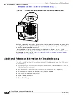
Cisco 7505 Power Supply LED

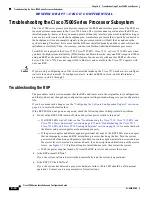
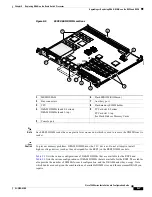
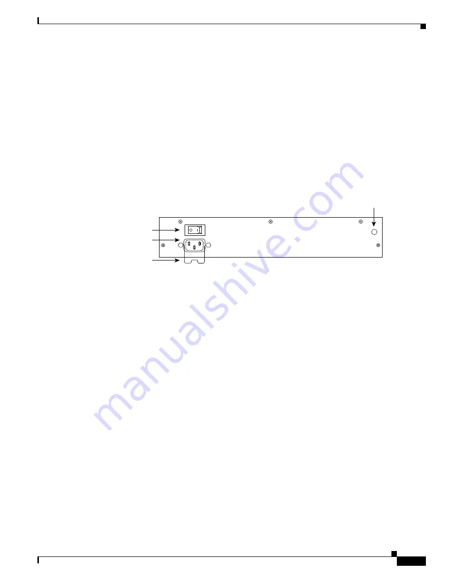
The DC OK LED (see 

Figure 8-8

) on the interface processor end of the Cisco 7505 AC-input and 

DC-input power supplies goes on when the power supply is receiving AC or DC source power and 
providing DC power to the internal chassis components. The power supply self-monitors its own 
temperature and internal voltages. (For detailed descriptions of the show commands that display 
temperature and voltage information, see the 

“Cisco 7505 Environmental show Command Examples” 

section on page 2-27

.) 

Figure 8-8

Power Supply LED (AC-Input Power Supply Shown, Cisco 7505)

Cisco 7507 and Cisco 7507-MX Power Supply LEDs

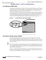
There are two types of power supplies for the Cisco 7507 and Cisco 7507-MX: AC-input and DC-input. 
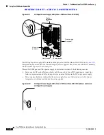
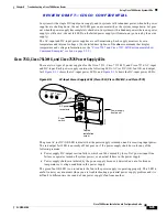
Each AC-input power supply has AC power and DC fail LEDs and a power switch, as shown in 

Figure 8-9

. The green AC power LED indicates that the power supply is turned on and is receiving input 

AC power. The yellow DC fail LED is normally off, but goes on if the power supply shuts down for any 
of the following reasons:   

Power supply DC section failure, which could be caused by loss of source (AC or DC) power (input 
line failure or operator turned off system power) or an actual failure in the power supply

Power supply shutdown initiated by the power supply because it detected an out-of-tolerance 
temperature or voltage condition in the power supply

In systems with a single AC-input power supply, and in systems with redundant power, when both 
AC-input power supplies are being shut down, the DC fail LED goes on momentarily as the system 
ramps down, but is off when the power supply has completely shut down. In systems with redundant 
power where one power supply is still active, the DC fail LED on the failed power supply will remain 
on (powered by the active supply).

AC receptacle

On/off switch

Cable retention 
clip

DC OK  LED

H1998

Summary of Contents for 7505

Page 1: ...ems Inc 170 West Tasman Drive San Jose CA 95134 1706 USA http www cisco com Tel 408 526 4000 800 553 NETS 6387 Fax 408 526 4100 Cisco 7500 Series Installation and Configuration Guide Customer Order Number Text Part Number OL 5008 03 B0 ...

Page 2: ... measures Turn the television or radio antenna until the interference stops Move the equipment to one side or the other of the television or radio Move the equipment farther away from the television or radio Plug the equipment into an outlet that is on a different circuit from the television or radio That is make certain the equipment and the television or radio are on circuits controlled by diffe...

Page 3: ...rvice Request xxi Definitions of Service Request Severity xxi Obtaining Additional Publications and Information xxii C H A P T E R 1 Cisco 7500 Series Product Overview 1 1 Terms and Acronyms 1 2 Cisco 7505 Overview 1 3 Cisco 7505 CyBus Backplane 1 4 Cisco 7505 System Specifications 1 5 Cisco 7507 Overview 1 6 Cisco 7507 Dual CyBus Backplane 1 8 Cisco 7507 System Specifications 1 10 Cisco 7507 MX O...

Page 4: ...1 39 Common RSP Hardware Features 1 42 RSP LEDs 1 42 RSP DRAM 1 42 RSP SRAM 1 43 RSP NVRAM 1 43 RSP Flash Memory 1 43 RSP EEPROM 1 44 RSP Asynchronous Serial Ports Console and Auxiliary 1 44 AC Input and DC Input Power Supply Overview 1 46 Arbiter Overview 1 50 Chassis Interface Overview 1 50 Fan Tray and Blower Assembly Overview 1 51 Cisco 7505 Fan Tray Assembly 1 52 Cisco 7507 and Cisco 7507 MX ...

Page 5: ...Cisco 7500 Series Temperature and Voltage Thresholds 2 24 Cisco 7505 Temperature and Voltage Thresholds 2 24 Cisco 7507 and Cisco 7507 MX Temperature and Voltage Thresholds 2 25 Cisco 7513 Cisco 7513 MX and Cisco 7576 Temperature and Voltage Thresholds 2 25 Cisco 7500 Series Environmental Reports 2 26 Cisco 7505 Environmental show Command Examples 2 27 Cisco 7507 and Cisco 7507 MX Environmental sh...

Page 6: ...guration Register 4 4 Configuration Register Bit Meanings 4 5 Changing Configuration Register Settings 4 7 Booting the Cisco 7500 Series Router for the First Time 4 8 Using the Enable Secret and the Enable Password 4 8 Recovering a Lost Password 4 9 Configuring the Cisco 7500 Series System 4 11 Performing a Basic Configuration Using AutoInstall 4 11 Performing a Basic Manual Configuration Using th...

Page 7: ...s Interface in the Cisco 7505 5 11 Removing and Replacing the Cisco 7505 Power Supply 5 13 C H A P T E R 6 Maintaining Your Cisco 7507 and Cisco 7507 MX Router 6 1 Tools Required for Maintenance Procedures 6 2 Overview of Maintenance Procedures for the Cisco 7507 and Cisco 7507 MX 6 2 Maintenance Procedures for the Cisco 7507 and Cisco 7507 MX 6 3 Removing Cisco 7507 and Cisco 7507 MX Power Suppli...

Page 8: ...ting Guidelines for the Cisco 7507 and Cisco 7507 MX 8 8 Identifying Cisco 7507 and Cisco 7507 MX Startup Problems 8 9 Troubleshooting the Cisco 7507 and Cisco 7507 MX Power Subsystem 8 10 Troubleshooting the Cisco 7507 and Cisco 7507 MX Cooling Subsystem 8 11 Troubleshooting Guidelines for the Cisco 7513 Cisco 7513 MX and Cisco 7576 8 12 Identifying Cisco 7513 Cisco 7513 MX and Cisco 7576 Startup...

Page 9: ...P2 SIMMs 9 4 Upgrading or Replacing DRAM DIMMs on the RSP4 and RSP8 9 5 Removing RSP4 and RSP8 DIMMs 9 9 Installing New RSP4 or RSP8 DIMMs 9 10 A P P E N D I X A Configuration Register Information A 1 Configuration Bit Meanings A 1 Bits 0 3 A 2 Bit 6 A 3 Bit 7 A 3 Bit 8 A 4 Bit 10 and Bit 14 A 4 Bit 11 and Bit 12 A 4 Bit 13 A 4 Bit 15 A 5 Displaying the Configuration Register While Running Cisco I...

Page 10: ...Contents x Cisco 7500 Series Installation and Configuration Guide OL 5008 03 B0 ...

Page 11: ...dividually packaged you need to install these in your system After you install the hardware and perform a basic system configuration you will then use the appropriate software configuration publications and companion publications to more completely configure your system and its interfaces Audience Setting up and maintaining a network requires the knowledge and expertise of people with a variety of...

Page 12: ...onal sections for each Cisco 7500 series router Chapter 4 Performing a Basic Configuration of the System Provides simple procedures for completing a basic system configuration of your Cisco 7500 series router and for checking and saving this configuration to system memory Chapter 5 Maintaining Your Cisco 7505 Router Describes the procedures required to perform routine maintenance and to remove and...

Page 13: ...versatile inteface processors port adapters and so forth The documentation flyer includes links to these documents Information is available online on the Documentation CD ROM or as printed copies Conventions This document uses the conventions listed in Table 1 Notes use the following conventions Table 1 Conventions Convention Description boldface font Commands and keywords are in boldface italic f...

Page 14: ...n save time by performing the action described in the paragraph Tips use the following conventions Tip Means the following are useful tips Cautions use the following conventions Caution Means reader be careful In this situation you might do something that could result in equipment damage or loss of data Warnings use the following conventions Warning Safety warnings appear throughout this publicati...

Page 15: ...an de bij elektrische schakelingen betrokken risico s en dient u op de hoogte te zijn van de standaard praktijken om ongelukken te voorkomen Voor een vertaling van de waarschuwingen die in deze publicatie verschijnen dient u de vertaalde veiligheidswaarschuwingen te raadplegen die bij dit apparaat worden geleverd Opmerking BEWAAR DEZE INSTRUCTIES Opmerking Deze documentatie dient gebruikt te worde...

Page 16: ...Gebrauch in Verbindung mit dem Installationshandbuch für Ihr Gerät bestimmt das dem Gerät beiliegt Entnehmen Sie bitte alle weiteren Informationen dem Handbuch Installations oder Konfigurationshandbuch o Ä für Ihr spezifisches Gerät Figyelem FONTOS BIZTONSÁGI ELÕÍRÁSOK Ez a figyelmezetõ jel veszélyre utal Sérülésveszélyt rejtõ helyzetben van Mielõtt bármely berendezésen munkát végezte legyen figye...

Page 17: ...tação destina se a ser utilizada em conjunto com o manual de instalação incluído com o produto específico Consulte o manual de instalação o manual de configuração ou outra documentação adicional inclusa para obter mais informações Advertencia INSTRUCCIONES IMPORTANTES DE SEGURIDAD Este símbolo de aviso indica peligro Existe riesgo para su integridad física Antes de manipular cualquier equipo consi...

Page 18: ...pecial tool lock and key or other means of security and is controlled by the authority responsible for the location Waarschuwing Dit toestel is bedoeld voor installatie op plaatsen met beperkte toegang Een plaats met beperkte toegang is een plaats waar toegang slechts door servicepersoneel verkregen kan worden door middel van een speciaal instrument een slot en sleutel of een ander veiligheidsmidd...

Page 19: ...um kontrolliert wird Avvertenza Questa unità deve essere installata in un area ad accesso limitato Un area ad accesso limitato è un area accessibile solo a personale di assistenza tramite un attrezzo speciale lucchetto o altri dispositivi di sicurezza ed è controllata dall autorità responsabile della zona Advarsel Denne enheten er laget for installasjon i områder med begrenset adgang Et område med...

Page 20: ...tation through a local account representative by calling Cisco Systems Corporate Headquarters California USA at 408 526 7208 or elsewhere in North America by calling 800 553 NETS 6387 Documentation Feedback You can send comments about technical documentation to bug doc cisco com You can submit comments by using the response card if present behind the front cover of your document or by writing to t...

Page 21: ...o TAC by telephone S1 or S2 service requests are those in which your production network is down or severely degraded Cisco TAC engineers are assigned immediately to S1 and S2 service requests to help keep your business operations running smoothly To open a service request by telephone use one of the following numbers Asia Pacific 61 2 8446 7411 Australia 1 800 805 227 EMEA 32 2 704 55 55 USA 1 800...

Page 22: ... quarter Packet delivers coverage of the latest industry trends technology breakthroughs and Cisco products and solutions as well as network deployment and troubleshooting tips configuration examples customer case studies certification and training information and links to scores of in depth online resources You can access Packet magazine at this URL http www cisco com packet iQ Magazine is the qu...

Page 23: ...age 1 20 Cisco 7576 Overview page 1 25 Note The Cisco 7513 Cisco 7513 MX and the Cisco 7576 are similar in appearance To determine which router you have look at the slot numbering label on the back of the unit The Cisco 7513 MX and Cisco 7576 are identified as such on the slot numbering label The remaining sections of this chapter describe components in the Cisco 7500 series routers which are cons...

Page 24: ...has an aggregate bandwidth of 2 134 Gbps Interface processors designed for the CxBus work with the CyBus dBus Diagnostic bus for Route Switch Processor diagnostic and control access system discovery and control microcode download and fault diagnosis for all processors connected to the CyBus DIMM Dual in line memory module DRAM Dynamic random access memory EIP Ethernet Interface Processor FEIP Fast...

Page 25: ...r incorporates the same features as the VIP2 but with higher distributed switching increased bandwidth and features such as high availability and high service availability which further reduces system downtime VIP6 80 The VIP6 80 improves performance over previous versatile interface processors Cisco 7505 Overview The Cisco 7505 supports multiprotocol multimedia routing and bridging with a wide va...

Page 26: ... and interface processors and transfers information at up to 1 067 Gbps The Cisco 7505 CyBus backplane has five slots interface processor slots 0 through 3 and one slot for the RSP RSP2 RSP4 4 or RSP8 as shown in Figure 1 3 H2009 Captive fasteners H2761 RSP slot DC OK LED Power switch Chassis grounding receptacles Power receptacle AC input power supply E J E C T S L O T 0 S L O T 1 N O R M A L C P...

Page 27: ... 3 SLOT 2 SLOT 1 SLOT 0 H2875 Table 1 1 Cisco 7505 Specifications Description Specification High speed backplane 1 067 Gbps CyBus 4 interface processor slots and 1 RSP slot Dimensions H x W x D 10 5 x 17 5 x 17 0 in 26 67 x 44 45 x 43 18 cm Chassis depth including power cord and cable management brackets is 19 in 48 26 cm Weight Chassis only including power supply and fan array 46 lb 20 87 kg Chas...

Page 28: ...wn in Figure 1 4 contains three status indicators and two removable panels for access to the internal components The three light emitting diodes LEDs on the front panel indicate normal system operation and the currently active power supplies On the back of the router a normal LED on the RSP and LEDs on the power supplies indicate the same status DC input rating 40 VDC minimum in North America 56 V...

Page 29: ...ies Installation and Configuration Guide OL 5008 03 B0 Chapter 1 Cisco 7500 Series Product Overview Cisco 7507 Overview Figure 1 4 Cisco 7507 Front View UPPER POWER LOWER POWER NORMAL H3135 UPPER POWER LOWER POWER NORMAL ...

Page 30: ...face processors and transfers information at up to 2 134 Gbps 1 067 Gbps per CyBus The dual CyBus has seven slots interface processor slots 0 and 1 CyBus 0 RSP slots 2 and 3 and interface processor slots 4 through 6 CyBus 1 as shown in Figure 1 6 ENABLE ENABLE EJECT SLOT 0 SLOT 1 NORMAL CPU HALT RESET AUX CONSOLE ROUTE SWITCH PROCESSOR 2 SLAVE MASTER SLAVE M ASTER H3888 Slot 0 1 2 3 4 5 6 Upper po...

Page 31: ...rs connected to one CyBus are unaffected by the traffic generated by the interface processors connected to the other The backplane slots are keyed so that the processor modules can be installed only in the slots designated for them Keys on the backplane fit into two key guides on each module Although the RSP uses unique keys all five interface processor slots use the same key so you can install an...

Page 32: ...nput voltage 100 to 240 VAC wide input with power factor corrector PFC AC input cable 12 AWG with 3 leads an IEC 320 plug on the router end and a country dependent plug on the power source end Frequency 50 to 60 Hz autoranging AC input ratings 10A maximum 100 VAC 6A maximum 240 VAC chassis fully configured DC input ratings 40 VDC minimum 48 VDC nominal 72 VDC maximum Power distribution 5 2 VDC 95A...

Page 33: ...essor slot There are bays for up to two AC input or DC input power supplies The chassis will operate with one power supply Although a second power supply is not required it allows load sharing and increased system availability Caution Because of agency compliance and safety issues mixing AC input and DC input power supplies in the same Cisco 7507 MX is not a supported configuration and should not ...

Page 34: ...d interface processors and transfers information at up to 2 134 Gbps 1 067 Gbps per CyBus The dual CyBus has seven slots interface processor slots 0 and 1 CyBus 0 RSP slots 2 and 3 and interface processor slots 4 through 6 CyBus 1 as shown in Figure 1 9 ENABLE ENABLE EJECT SLOT 0 SLOT 1 NORMAL CPU HALT RESET AUX CONSOLE ROUTE SWITCH PROCESSOR 2 SLAVE MASTER SLAVE M ASTER H3888 Slot 0 1 2 3 4 5 6 U...

Page 35: ...n RSP2 RSP4 4 or RSP8 in either slot 2 or slot 3 controls both CyBus 0 and CyBus 1 The dual CyBus backplane in the Cisco 7507 MX has an aggregate bandwidth of 2 134 Gbps The two CyBuses are independent of one another Interface processors connected to one CyBus are unaffected by the traffic generated by the interface processors connected to the other The backplane slots are keyed so that the proces...

Page 36: ... AC input voltage 100 to 240 VAC wide input with power factor corrector PFC AC input cable 12 AWG with 3 leads an IEC 320 plug on the router end and a country dependent plug on the power source end Frequency 50 to 60 Hz autoranging AC input ratings 10A maximum 100 VAC 6A maximum 240 VAC chassis fully configured DC input ratings 40 VDC minimum 48 VDC nominal 72 VDC maximum Power distribution 5 2 VD...

Page 37: ...ocessor RSP2 RSP4 4 RSP8 or RSP16 slots 6 and 7 and interface processor slots 8 through 12 The Cisco 7513 supports 11 VIPs one for each interface processor slot There are bays for up to two AC input or DC input power supplies The chassis will operate with one power supply Although a second power supply is not required it allows load sharing and increased system availability Caution Because of agen...

Page 38: ...o 7500 Series Installation and Configuration Guide OL 5008 03 B0 Chapter 1 Cisco 7500 Series Product Overview Cisco 7513 Overview Figure 1 10 Cisco 7513 Front View 122303 POWER A POWER B NORMAL Front panel LEDs ...

Page 39: ...e RSPs and interface processors and transfers information at up to 2 134 Gbps 1 067 Gbps per CyBus The dual CyBus has 13 slots interface processor slots 0 through 5 CyBus 0 two RSP slots slots 6 and 7 interface processor slots 8 through 12 CyBus 1 as shown in Figure 1 12 ENABLE ENABLE 122373 EJE CT SLO T 0 SLO T 1 NORMAL CPU HALT RESET AUX CONSOLE ROUTE SWITCH PROCESSOR 2 SLA VE MASTER SLA VE M AS...

Page 40: ...ndependent of one another The backplane slots are keyed so that the processor modules can be installed only in the slots designated for them Keys on the backplane fit into two key guides on each module Although the RSP uses unique keys all eleven interface processor slots use the same key so you can install an interface processor in any interface processor slot but not in the RSP slot Note A spare...

Page 41: ...sco 7513 requires a minimum of 20A service with a 20A receptacle at the power source The power cable supplied with the Cisco 7513 uses a 20A male plug 12 AWG with 3 leads an IEC 320 plug on the router end and a country dependent plug on the power source end AC input voltage and current 100 VAC at 16 amps A maximum wide input with power factor corrector PFC 240 VAC at 7A maximum DC input voltage an...

Page 42: ... Processor RSP2 RSP4 4 RSP8 or RSP16 slots 6 and 7 and interface processor slots 8 through 12 The Cisco 7513 MX supports 11 VIPs one for each interface processor slot There are bays for up to two AC input or DC input power supplies The chassis will operate with one power supply Although a second power supply is not required it allows load sharing and increased system availability Caution Because o...

Page 43: ...500 Series Installation and Configuration Guide OL 5008 03 B0 Chapter 1 Cisco 7500 Series Product Overview Cisco 7513 MX Overview Figure 1 13 Cisco 7513 MX Front View 122303 POWER A POWER B NORMAL Front panel LEDs ...

Page 44: ... for the RSPs and interface processors and transfers information at up to 2 134 Gbps 1 067 Gbps per CyBus The dual CyBus has 13 slots interface processor slots 0 through 5 CyBus 0 two RSP slots slots 6 and 7 interface processor slots 8 through 12 CyBus 1 as shown in Figure 1 15 ENABLE ENABLE 122374 EJE CT SLO T 0 SLO T 1 NORMAL CPU HALT RESET AUX CONSOLE ROUTE SWITCH PROCESSOR 2 SLA VE MASTER SLA ...

Page 45: ...us backplane in the Cisco 7513 MX has an aggregate bandwidth of 2 134 Gbps Interface processors connected to one CyBus are unaffected by the traffic generated by the interface processors connected to the other CyBus The two CyBuses are independent of one another The backplane slots are keyed so that the processor modules can be installed only in the slots designated for them Keys on the backplane ...

Page 46: ...t cable1 1 The Cisco 7513 MX requires a minimum of 20A service with a 20A receptacle at the power source The power cable supplied with the Cisco 7513 MX uses a 20A male plug 12 AWG with 3 leads an IEC 320 plug on the router end and a country dependent plug on the power source end AC input voltage and current 100 VAC at 16 amps A maximum wide input with power factor corrector PFC 240 VAC at 7A maxi...

Page 47: ...Cisco 7576 supports 10 VIPs one for each interface processor slot 6 VIPs are supported in Router A and 5 VIPs are supported in Router B There are bays for up to two AC input or DC input power supplies The chassis will operate with one power supply Although a second power supply is not required it allows load sharing and increased system availability Caution Because of agency compliance and safety ...

Page 48: ...o 7500 Series Installation and Configuration Guide OL 5008 03 B0 Chapter 1 Cisco 7500 Series Product Overview Cisco 7576 Overview Figure 1 16 Cisco 7576 Front View 122303 POWER A POWER B NORMAL Front panel LEDs ...

Page 49: ...o 7576 Dual CyBus Backplane The Cisco 7576 features two dual CyBuses creating two independent routers on one split backplane The dual CyBus backplane located at the rear of the removable card cage provides the physical connections for the RSPs and interface processors and transfers information at up to 2 134 Gbps 1 067 Gbps per CyBus per router EJE CT SLO T 0 SLO T 1 NORMAL CPU HALT RESET AUX CONS...

Page 50: ...8 Cisco 7576 Dual CyBus Backplane Note The Cisco 7576 backplane includes connectors for time division multiplexing TDM compatible hardware These connectors allow you to connect the Cisco 7576 to future TDM hardware as it becomes available The backplane slots are keyed so that the processor modules can be installed only in the slots designated for them Keys on the backplane fit into two key guides ...

Page 51: ...grounds identifies router B components CyBus 2 is assigned interface processor slots 8 10 and 12 dark gray on yellow CyBus 3 is assigned interface processor slots 9 and 11 dark gray on light green The RSP for router B is assigned slot 7 dark gray on white Figure 1 19 Enlarged View of the Cisco 7576 Interface Processor Slot Numbering Scheme Note To provide a viewable image slot numbers 0 1 2 11 and...

Page 52: ...either 2 AC input or 2 DC input power supplies Heat dissipation 1600W 5461 Btu hr AC input voltage 100 to 240 VAC Frequency 50 60 Hz AC input cable1 1 The Cisco 7576 requires a minimum of 20A service with a 20A receptacle at the power source The power cable supplied with the Cisco 7576 uses a 20A male plug 12 AWG with 3 leads an IEC 320 plug on the router end and a country dependent plug on the po...

Page 53: ... all RSPs RSP Specific Hardware Features The following sections describe hardware features that are specific to each of the RSPs used in the Cisco 7500 series Select the appropriate section based on the RSP and Cisco 7500 series router that you have RSP2 Cisco 7505 page 1 31 RSP4 4 Cisco 7507 Cisco 7513 and Cisco 7576 page 1 33 RSP8 Cisco 7507 MX and Cisco 7513 MX page 1 36 RSP16 Cisco 7507 Cisco ...

Page 54: ...on register so you do not have to remove the RSP2 to configure jumpers There are no user configurable jumpers on the RSP2 The RSP2 contains the following components R4600 Reduced Instruction Set Computing RISC processor used for the CPU The CPU runs at an external clock speed of 50 MHz and an internal clock speed of 100 MHz Most of the memory components used by the system including onboard Flash m...

Page 55: ...ists the functions of each type of memory on the RSP2 Note For RSP2 DRAM upgrade procedures see Chapter 9 Replacing DRAM on the Route Switch Processor RSP4 4 Cisco 7507 Cisco 7513 and Cisco 7576 The RSP4 4 shown in Figure 1 21 is the main system processor for the Cisco 7507 Cisco 7513 and Cisco 7576 routers The RSP4 4 provides switched routing and high speed switching functions Table 1 7 RSP2 Memo...

Page 56: ...r temperature is done by the RSP4 4 a comparator device ensures that 12V is maintained within the normal operating ranges and three temperature sensors on the RSP4 4 send temperature information to the chassis interface CI card The CI card reports all voltage and temperature readings and these readings are available through standard software commands for environmental monitoring The RSP4 4 uses a ...

Page 57: ...g all of the switched routing and high speed switching functions that communicate with and control the interface processors on the dual CyBus This switching section decides the destination of a packet and switches it accordingly The RSP4 4 supports high system availability HSA which is a feature in Cisco IOS Release 11 1 4 or later allowing two RSPs to be used in a Cisco 7507 Cisco 7507 MX Cisco 7...

Page 58: ... Figure 1 17 Table 1 8 RSP4 4 Memory Components Type Size Quantity Description Location DRAM 321 to 256 MB DIMMs 1 32 MB is the default DRAM configuration for the RSP4 4 1 or 2 32 64 or 128 MB DIMMs based on DRAM required for main Cisco IOS image functions U10 or U10 and U13 SRAM2 2 SRAM is not user configurable or field replaceable 2 MB fixed SRAM for packet buffering functions MEMD 512 KB fixed ...

Page 59: ...ing The RSP8 uses a software controlled configuration register so you do not have to remove the RSP8 to configure jumpers There are no user configurable jumpers on the RSP8 The RSP8 contains the following components R7000 Reduced Instruction Set Computing RISC processor used for the CPU with 256 KB on chip secondary L2 cache The CPU runs at an external bus clock speed of 100 MHz and an internal cl...

Page 60: ...rols the interface processors on the high speed CyBus This switching section of the RSP8 decides the destination of a packet and switches it based on that decision The RSP8 combines all of the switched routing and high speed switching functions The RSP8 supports the HSA feature which allows two RSP8s to be used in a Cisco 7507 Cisco 7507 MX Cisco 7513 or Cisco 7513 MX router By default the system ...

Page 61: ...he RSP16 In the form of a single in line memory module SIMM U1 in Figure 2 Up to two Flash Disks that insert in the two PC Card slots slot 0 and slot 1 Table 1 9 RSP8 Memory Components Type Size Quantity Description Location DRAM 64 MB1 to 256 MB DIMMs 1 64 MB of DRAM is the default DRAM configuration for the RSP8 The board is preconfigured with either two 32 MB DIMMs or one 64 MB DIMM 1 or 2 Any ...

Page 62: ... devices Figure 1 23 Route Switch Processor RSP16 The RSP16 also contains Most of the additional memory components used by the system including 16 MB onboard Flash memory and up to two Flash Disks 48 MB 64 MB or 128 MB per Flash Disk with the 48 MB Flash Disk being the shipping default 1 Queues and Accumulators QA ASIC U39 8 2 MEMD Control MC ASIC 9 3 dBus FPGA 10 PC card slot 0 bottom PC card slo...

Page 63: ...the HA features You have no restrictions on installing an RSP16 in a Cisco 7507 or Cisco 7507 MX provided that you install the RSP16 in slot 2 slot 3 or both With the HSA or HA features enabled you will install an RSP16 or an RSP8 and an RSP16 in both RSP slots You have no restrictions on installing an RSP16 in a Cisco 7513 or Cisco 7513 MX provided that you install the RSP16 in slot 6 slot 7 or b...

Page 64: ...the respective PC Card slot Note The master slave LED and the HSA feature are not supported on the Cisco 7505 or Cisco 7576 RSP DRAM Dynamic random access memory DRAM stores routing tables protocols and network accounting applications Table 1 11 lists the RSP DRAM configurations 2 Do not mix memory sizes If installing 2 DIMMs both DIMMs must be the same size If your router includes redundant RSPs ...

Page 65: ...dure is not necessary if you are temporarily removing an RSP you will reinstall lithium batteries retain the configuration in memory until you replace the RSP in the system RSP Flash Memory Flash memory either on a SIMM or on a Flash memory PC Card or Flash Disk allows you to remotely load and store multiple Cisco IOS software and microcode images and to back up configurations on your Cisco 7500 s...

Page 66: ...haracters rather than precise timing Serial interface ports on serial interface processors and port adapters support synchronous transmission which maintains precise clocking between the transmitter and receiver by sending frames of information that consist of separate clock signals along with the data signals Note When connecting serial devices ensure that the devices support the proper transmiss...

Page 67: ...7507 MX and RSP slots 6 and 7 in the Cisco 7513 and Cisco 7513 MX Note The Cisco 7576 does not support master slave configuration In the Cisco 7576 the RSP in slot 6 is automatically the system master for router A and the RSP in slot 7 is automatically the system master for router B The use of Y cables is not supported on the Cisco 7576 and they are not included with the unit The two Y cables ship...

Page 68: ... End DB 25 Pins Male End DB 25 Pins Description P1 1 J1 1 and J2 1 Ground GND P1 2 J1 2 and J2 2 Receive Data RxD P1 3 J1 3 and J2 3 Transmit Data TxD P1 4 J1 4 and J2 4 Clear To Send CTS looped to 5 P1 5 J1 5 and J2 5 Request To Send RTS looped to 4 P1 6 J1 6 and J2 6 Data Set Ready DSR P1 7 J1 7 and J2 7 Ground GND P1 8 J1 8 and J2 8 Data Carrier Detect DCD P1 13 J1 13 and J2 13 YCBL Detect Grou...

Page 69: ...pecifications are listed in Table 1 1 Cisco 7505 Table 1 2 Cisco 7507 Table 1 3 Cisco 7507 MX Table 1 4 Cisco 7513 Table 1 5 Cisco 7513 MX and Table 1 6 Cisco 7576 For Cisco 7500 series routers used in North America the following AC input and DC input power supplies are available Cisco 7505 Product Numbers PWR 5AC see Figure 1 24 and PWR 5DC see Figure 1 25 Cisco 7507 and Cisco 7507 MX Product Num...

Page 70: ... 27 DC Input Power Supply Cisco 7507 and Cisco 7507 MX Figure 1 28 AC Input Power Supply Cisco 7513 Cisco 7513 MX and Cisco 7576 I 0 D C FA IL AC PO W ER H1356a Captive installation screw H2496 I O O U T FA IL IN PU T PO W ER DO NOT SHIP WITH POWER SUPPLY INSTALLED FASTENER TO BE FULLY ENGAGED BEFORE OPERATING POWER SUPPLY INPUT VOLTAGE 40 72 V INPUT CURRENT 24 13A NO SERVICEABLE COMPONENTS INSIDE...

Page 71: ...mbers PWR 7513 ACU PWR 7513 ACA PWR 7513 ACI PWR 7513 ACE DC input Product Numbers PWR 7513 DCU PWR 7513 DCA PWR 7513 DCI PWR 7513 DCE Cisco 7576 AC input Product Numbers PWR 7576 ACU PWR 7576 ACA PWR 7576 ACI PWR 7576 ACE DC input Product Numbers PWR 7576 DCU PWR 7576 DCA PWR 7576 DCI PWR 7576 DCE The AC input and DC input power supplies available for countries outside North America differ from t...

Page 72: ...vate copy of the clock to the RSP and each interface processor CyBus arbitration Arbitrates interface processor requests to transmit commands on the CyBus The arbitration is based on a round robin priority scheme to ensure that all interface processors have access to a known portion of each CyBus s bandwidth Global lock arbitration Arbitrates interface processor and RSP requests for the global loc...

Page 73: ...temperature setpoint is changed to a very low value preventing the affected router from powering back up This achieves a hard shutdown of one router without affecting the other router The RSP and interface processors will remain disabled until the power is manually recycled This allows you to choose a suitable time to recycle the power when it will not adversely affect your users For CI maintenanc...

Page 74: ...fied range A variable speed feature allows the fans to operate at a slower speed when the internal chassis temperature is within the normal operating range and at a higher speed if the internal temperature exceeds a specified temperature A spare fan tray ships as Product Number MAS 5 FAN For fan tray maintenance information see the Removing and Replacing the Cisco 7505 Fan Tray section on page 5 5...

Page 75: ...r module assembly also contains the system LEDs which are located on a nonremovable printed circuit card at the rear of the interior of the blower module assembly A spare blower module assembly ships as Product Numbers MAS 7513 FAN for the Cisco 7513 and Cisco 7513 MX and MAS 7576 FAN for the Cisco 7576 For blower module assembly maintenance information see the Removing and Replacing the Cisco 751...

Page 76: ... it is installed supports downloadable microcode which enables you to download new microcode images remotely and store them in Flash memory You can then use software commands to load a specific microcode image from Flash memory Each interface processor has a unique bank of status LEDs and all have a common LED called the enabled LED on the interface processor s faceplate The enabled LED lights whe...

Page 77: ...nterface Processor with one SONET SDH STS 3c single mode or multimode interface TRIP Token Ring Interface Processor with two or four high speed 4 and 16 Mbps Token Ring interfaces VIP2 VIP4 Second Generation and Fourth Generation Versatile Interface Processor with many combinations of the following interfaces and services available by way of up to two interchangeable port adapters and service adap...

Page 78: ...ocode images then decompresses the images into running memory DRAM The bundled microcode images then function the same as images loaded from the microcode EPROM The Cisco 7500 series routers support downloadable Cisco IOS software and interface processor microcode images which enables you to remotely download store and boot from a new image The Cisco IOS image runs from the DRAM on the RSP interfa...

Page 79: ...all items for shipping damage If anything is damaged immediately contact a customer service representative Sections in this chapter include the following Tools and Parts You Need page 2 1 Safety Recommendations page 2 2 AC Input and DC Input Power Guidelines page 2 7 Plant Wiring Guidelines page 2 10 Site Environment Chassis Temperature and Airflow Guidelines page 2 12 Equipment Rack Mounting Guid...

Page 80: ...ure your safety and protect your equipment This list is not inclusive of all potentially hazardous situations so be alert Always turn all power supplies off O and unplug all power cables before opening the chassis Keep the chassis area clear and dust free during and after installation Keep tools and chassis components away from walk areas Do not wear loose clothing jewelry including rings and chai...

Page 81: ...refully examine your work area for possible hazards such as moist floors ungrounded power extension cables and missing safety grounds In addition use the guidelines that follow when working with any equipment that is disconnected from a power source but still connected to telephone or network wiring Never install telephone wiring during a lightning storm Never install telephone jacks in wet locati...

Page 82: ...the chassis bend at the knees not at the waist to reduce the strain on your lower back muscles Whenever possible lift a chassis from the bottom grasp the underside of the chassis exterior with both hands Always disconnect all external cables before lifting or moving the chassis For the Cisco 7507 Cisco 7507 MX Cisco 7513 Cisco 7513 MX and Cisco 7576 we recommend you lift the chassis with power sup...

Page 83: ... your legs as shown in Figure 2 2 Do not lift the chassis using the blower module handle or the air intake vent below the card cage Figure 2 2 Correct Way to Lift the Cisco 7513 Cisco 7513 MX or Cisco 7576 Caution To prevent damage to the air intake vent below the card cage do not lift the Cisco 7513 Cisco 7513 MX or Cisco 7576 by grasping the side handle with one hand and the bottom of the card c...

Page 84: ...nents are improperly handled and can result in intermittent or complete failures Always ensure that the chassis is electrically connected to earth ground Wear an ESD preventive wrist strap ensuring that it makes good skin contact To safely channel unwanted ESD voltages to ground connect the clip to an unpainted surface of the chassis frame If no wrist strap is available ground yourself to the meta...

Page 85: ...ng device is raised and clears the slot Also a retention clip prevents the AC input power supply power cable from being accidentally pulled out of the power supply socket For additional power supply information see the AC Input and DC Input Power Guidelines section on page 2 7 Check the power at your site before installation and periodically after installation to ensure that you are receiving clea...

Page 86: ...ed cable for the DC power connections See Table 1 2 and Table 1 3for a list of Cisco 7507 and Cisco 7507 MX power specifications Note The Cisco 7507 or Cisco 7507 MX installation must comply with all applicable codes and is approved for use with copper conductors only The ground bond fastening hardware should be of compatible material and preclude loosening deterioration and electrochemical corros...

Page 87: ...eaded M5 chassis grounding receptacles These receptacles are intended to be bonded directly to the central office or other interior ground system and are located on the rear of the chassis The chassis grounding receptacles require M5 screws and locking hardware which are not included A second identical power supply is also present in routers configured with the redundant power option this ensures ...

Page 88: ...electromagnetic interference and connector compatibility as described in the sections that follow Interference Considerations with Cabling When wires are run for any significant distance in an electromagnetic field interference can occur between the field and the signals on the wires This fact has two implications for the construction of plant wiring Bad practices can result in radio interference ...

Page 89: ... closed loop or spade type with upturned lugs These terminations should be the appropriate size for the wires and should clamp both the insulation and conductor Warning To be installed and maintained by service personnel as defined by AS NZS 3260 Incorrect connection of this or connected equipment to a General Purpose Outlet could result in a hazardous situation The telecommunication lines must be...

Page 90: ...isco 7500 Series section on page 2 22 If the temperature of the air drawn into the chassis is higher than desirable the air temperature inside the chassis might also be too high This condition can occur when the wiring closet or rack in which the chassis is mounted is not ventilated properly when the exhaust of one device is placed so it enters the air inlet vent of the chassis or when the chassis...

Page 91: ...nside the chassis A temperature sensor on the RSP monitors the internal air temperature The power supply has two fans for cooling Figure 2 7 shows the chassis fans and airflow through the Cisco 7505 Figure 2 7 Airflow Through the Cisco 7505 Humidity ambient noncondensing nonoperating and storage 5 95 Altitude operating and nonoperating Sea level 10 000 ft 3050 m Vibration operating 5 to 200 Hz 0 5...

Page 92: ...Cisco 7507 and Cisco 7507 MX Figure 2 8 Airflow Through the Cisco 7507 and Cisco 7507 MX Sensors on the RSP2 for example monitor the inlet and internal chassis air temperatures If the air temperature at either of the sensors exceeds a desired threshold an environmental monitor displays warning messages and can interrupt system operation to protect the system components from possible damage from ex...

Page 93: ...Ventilation Considerations If you plan to install the router in an equipment rack you can avoid overtemperature conditions by observing the following precautions There must be at least 2 inches 5 08 cm of clearance between each side of the chassis and the side or inner wall of an enclosed rack Enclosed racks must have adequate ventilation or an exhaust fan use an open rack whenever possible A vent...

Page 94: ...uch as a power strip that could impair access to the interface processors or chassis cover panel As an alternative the router can be mounted on an equipment shelf provided that the rack dimensions allow the router to be secured to the shelf and the overall configuration permits safe installation and access Figure 2 10 shows the chassis footprint and outer dimensions To use the rack mounting hardwa...

Page 95: ...ust ports Avoid placing the router in an overly congested rack or directly next to another equipment rack Otherwise the heated exhaust from other equipment can enter the inlet air vents and cause an overtemperature condition inside the router Install and use the cable management brackets included with the router to keep cables organized and out of the way Consider the equipment and cabling that is...

Page 96: ...he mounting kit is not suitable for use with 2 post equipment racks or those with obstructions such as a power strip that could impair access to the interface processors and power supplies In telco environments or at installation sites that use nonstandard racks the router can be mounted on an equipment shelf provided that the rack dimensions allow safe installation and access to the power supplie...

Page 97: ...orts for cooling air are located on the front and rear of the chassis so multiple routers can be rack mounted with little or no vertical clearance However avoid placing the router in an overly congested rack Consider the equipment and cabling that is already installed in the rack Ensure that cables from other equipment will not obstruct the airflow through the chassis or impair access to the power...

Page 98: ...ess both the interface processor and noninterface processor ends of the router without having to remove the chassis from the rack The router can be mounted in the rear of a rack Before using a particular rack check for obstructions such as a power strip that could impair rack mount installation If a power strip does impair a rear rack mount installation remove the power strip before installing the...

Page 99: ...n equipment shelf ensure that the shelf is constructed to support the weight and dimensions of the chassis Figure 2 12 shows the chassis footprint which you will need if you are designing a customized shelf We recommend that you use the rack mount kit designed for the Cisco 7513 Cisco 7513 MX and Cisco 7576 Allow sufficient clearance around the rack for maintenance If the rack is mobile you can pu...

Page 100: ...3 Cisco 7513 MX or Cisco 7576 in a rack use the instructions in the configuration note Cisco 7513 and Cisco 7576 Rack Mount Kit Installation Instructions Document Number 78 2023 xx where xx indicates the latest document version which accompanies the rack mount kit The rack mount kit is the same for the Cisco 7507 Cisco 7507 MX Cisco 7513 Cisco 7513 MX and Cisco 7576 ACS 7000RMK In addition to the ...

Page 101: ...action is required Processor shutdown occurs when the chassis interface detects a temperature or blower failure condition that could result in physical damage to system components and has disabled DC power to all interface processors DC power to the RSP chassis interface and fans or blower stays on but no RSP related processing takes place Immediate action is required DC power remains off until th...

Page 102: ...ture and DC voltage in NVRAM so that you can retrieve them later as a report of the last shutdown parameters The power supplies monitor internal power supply temperature and voltages A power supply is either within tolerance Normal or out of tolerance Critical or Warning levels If an internal power supply temperature or voltage reaches a critical level the power supply shuts down without any inter...

Page 103: ...ocessor Monitored Temperature Thresholds Cisco 7505 Parameter Warning Normal Warning Critical Shutdown Inlet air 10 C 10 39 C 39 46 C 46 64 C 64 C Airflow 10 C 10 70 C 70 77 C 77 88 C 88 C Table 2 3 Typical Power Supply Monitored Voltage Thresholds Cisco 7505 Parameter Critical Normal Critical 5VDC 4 74 4 74 5 26 5 26 12VDC 10 20 10 20 to 13 8 13 80 12VDC 10 20 10 20 to 13 80 13 80 24VDC 20 00 20 ...

Page 104: ...ugh the chassis interior unimpeded Obstructing or blocking the air vents will restrict the airflow and can cause the internal chassis temperature to exceed acceptable limits The following sections include the environmental reporting and fan or blower functions for the Cisco 7500 series routers Cisco 7505 Environmental show Command Examples page 2 27 Cisco 7507 and Cisco 7507 MX Environmental show ...

Page 105: ...he system reports the worst case status level in the last line of the display instead of the status summary that is shown in the last line of the preceding example In the Cisco 7505 the show environment last command retrieves and displays the NVRAM log of the reason for the last shutdown and the environmental status at that time If no status is available it displays the reason as unknown Router sh...

Page 106: ...eters section of the table In this example the measured value at the inlet sensor is 41 C which falls within the warning range 39 C through 46 C and is therefore displayed in the Warning column Temperature Parameters SENSE WARNING NORMAL WARNING CRITICAL SHUTDOWN Inlet 10 39 41 C 46 64 Air flow 10 40 C 70 77 88 In the Cisco 7505 the show environment all command displays an extended report that inc...

Page 107: ... Environmental Monitor initiated shutdown Cisco 7507 and Cisco 7507 MX Environmental show Command Examples In the Cisco 7507 and Cisco 7507 MX the show environment command display reports the current environmental status of the system The report displays parameters that are out of the normal values No parameters are displayed if the system status is normal The example that follows shows the displa...

Page 108: ...r in the Cisco 7507 or Cisco 7507 MX the main system blower The system blower is designated 1 The active fault condition in the following example shows that there is no power supply installed in power bay A because the display indicates that power supply 1 in the lower bay is removed There are four active trip points restart OK temperature warning board shutdown and power supply shutdown There are...

Page 109: ...ll display the following message on the console screen and in the show environment command display when the system restarts Queued messages ENVM 1 SHUTDOWN Environmental Monitor initiated shutdown Cisco 7513 and Cisco 7513 MX Environmental show Command Examples In the Cisco 7513 and Cisco 7513 MX the show environment command display reports the current environmental status of the system The report...

Page 110: ...red at 4 82 V 12 volts measured at 12 00 V 24 volts measured at 23 90 V Air Flow temperature measured at 32 C Inlet temperature measured at 26 C RSP 6 Inlet previously measured at 27C 80F RSP 6 Hotpoint previously measured at 38C 100F RSP 6 Exhaust previously measured at 31C 87F 12 Voltage previously measured at 12 17 5 Voltage previously measured at 5 19 12 Voltage previously measured at 12 17 24...

Page 111: ...ommand displays an extended report that includes the arbiter type backplane type power supply type AC or DC wattage and status the number and type of intermittent power failures if any since the system was last powered on and the currently measured values at the RSP temperature sensors and the DC input lines The show environment all command also displays a report showing which slots in the Cisco 7...

Page 112: ...an has reached CRITICAL level Power Supply 1200W AC No Intermittent Powerfails 12 volts measured at 12 00 V 5 volts measured at 5 02 V 12 volts measured at 12 05 V 24 volts measured at 23 70 V Airflow temperature measured at 35 C Inlet temperature measured at 26 C Arbiter type 1 backplane type 7513 id 2 Power supply 1 is 1200W AC id 1 power supply 2 is removed id 7 Active fault conditions Blower 3...

Page 113: ...lows shows the display for a system in which all monitored parameters are within normal status range Following is sample output of the show env command Router show env All measured values are normal If the environmental status is not normal the system reports the worst case status level in the last line of the display In the Cisco 7576 the show environment last command retrieves and displays the N...

Page 114: ...and also reports which slots in the Cisco 7576 are occupied indicated by an X and which are empty Active fault conditions are indicated when the blower or power supply has failed or is not present The system expects to see three blowers or fans in the Cisco 7576 the main system blower and one fan in each power supply The system blower is designated 1 the power supply fan in power bay A is 2 and th...

Page 115: ...in the installation procedures we recommend that you also refer to the following sections in Chapter 2 Preparing for Installation Site Environment Chassis Temperature and Airflow Guidelines page 2 12 Equipment Rack Mounting Guidelines page 2 15 General Equipment Rack Ventilation Considerations page 2 15 Cisco 7505 Rack Mount Considerations page 2 16 Cisco 7507 and Cisco 7507 MX Rack Mount Consider...

Page 116: ...ommend that you see the next section Providing a Ground Connection for the Chassis and follow the procedure to provide a chassis ground connection Providing a Ground Connection for the Chassis Before you connect power or turn on power to your router we strongly recommend that you provide an adequate chassis ground earth connection for your router chassis Chassis grounding receptacles are provided ...

Page 117: ...wire approximately 0 75 inches 19 05 mm Step 3 Insert the 6 AWG wire into the top of the wire receptacle on the grounding lug See Figure 3 1 Step 4 Use the crimping tool to carefully crimp the wire receptacle around the wire this step is required to ensure a proper mechanical connection Step 5 Insert the screws through the holes in the grounding lug and into the chassis grounding receptacles See F...

Page 118: ...y Figure 3 2 shows a flowchart that illustrates the recommended order of procedures to install the Cisco 7505 router and attach external cables to it It also indicates the Cisco publications you should refer to for more detailed information Figure 3 2 Installation Flowchart Cisco 7505 Depending on your configuration you might need to insert additional or new processor modules in your Cisco 7505 To...

Page 119: ...erface processors as shown in the following illustration in any of the four interface processor slots numbered 0 through 3 from bottom to top when viewing the chassis from the rear See the illustration of the Cisco 7505 in Figure 1 2 The top slot slot 4 must contain the RSP which is a required system component The processor carriers are keyed so you cannot incorrectly install them in the chassis s...

Page 120: ...s shown in A 2 Simultaneously pull the ejector levers out to release the module from the backplane connector shown in B The levers should snap into their spring retainers 3 Grasp the module handle with one hand and place your other hand under the carrier to support and guide the module as you pull it out of the slot Avoid touching the card 4 Place the removed module on an antistatic mat or antista...

Page 121: ...supply push the cable retention clip away from the power receptacle and plug in the power cable Step 6 For a DC input power supply proceed to the Connecting Power to the Cisco 7505 DC Input Power Supply section on page 3 9 otherwise continue with Step 7 Step 7 Secure the cable in the power supply receptacle by pushing the cable retention clip until it snaps into place around the cable connector St...

Page 122: ...es the Cisco 7505 rack mount procedure Figure 3 4 Rack Mounting the Cisco 7505 H2908 18 312 46 51 cm hole centerline to hole centerline 17 72 min 45 cm Rack mount the chassis as follows 1 Measure the space between the vertical mounting strips on your rack Verify that your rack conforms to the measurements shown in A 2 Use the four M4 x 10 mm screws provided to attach the ears to the sides of the c...

Page 123: ...le but do not exceed the recommended minimum bend radius for your optical fiber cables Connecting Power to the Cisco 7505 DC Input Power Supply This section includes the procedure for connecting power to the Cisco 7505 DC input power supply The DC input power supply is already installed in the Cisco 7505 when you receive it This procedure assumes you ordered a DC input power supply with your Cisco...

Page 124: ...ure the cable leads to the terminal block cover See Figure 3 6c Step 5 Attach the RTN and 48V leads to the terminal block Note the color coding See Figure 3 6d Color code selection depends on the color code of the DC power source at your site Typically green or green yellow is used for ground black is used for RTN and red or white is used for 48V No matter which color coding is used make certain i...

Page 125: ...t Cisco 7507 and Cisco 7507 MX Depending on your configuration you might need to insert additional or new processor modules in your Cisco 7507 or Cisco 7507 MX To insert or remove interface processors you do not need to turn off power to the system However if the system is operating you must turn off the system power before you insert or remove an RSP2 RSP4 or RSP8 You need a number 1 Phillips or ...

Page 126: ...sco 7507 MX that has the high system availability HSA feature enabled and an RSP2 configured as the system slave online insertion and removal of any interface processor in either CyBus might cause the slave RSP2 to reboot with a bus error or a processor memory parity error The master RSP will recover from this event and issue a cBus Complex Restart message Cisco 7507 or Cisco 7507 MX systems that ...

Page 127: ...n the captive installation screws shown in A 2 Pull the ejector levers out to release the module from the backplane connector shown in B The levers should snap into their spring retainers 3 Grasp the module handle with one hand and place your other hand under the carrier to support and guide the module as you pull it out of the slot Avoid touching the card 4 Place the removed module in the board r...

Page 128: ...ocessors or by the plastic panels on the front of the chassis These handles were not designed to support the weight of the chassis Step 4 Two people are required to perform this step With a person positioned at either side of the chassis grasp the bottom edge of the chassis with one hand near the front and the other near the back Slowly lift the chassis in unison Avoid sudden twists or moves to pr...

Page 129: ... supply to separate input lines so in case of an input line failure the second source will most likely still be available If you install a second power supply in the upper bay use a screwdriver to loosen the captive screw and remove the cover plate Save the plate and replace it whenever the system is operating with one power supply Warning Before working on a chassis or working near power supplies...

Page 130: ...n screw at the top of the power supply before turning on the power switch This screw prevents the power supply from shifting away from the internal connector and provides proper grounding for the supply Step 7 For AC input power supplies push the cable retention clip away from the power receptacle and plug in the power cable Note For DC input power supplies proceed to the Connecting Power to Cisco...

Page 131: ... cord on AC units or disconnect the power at the circuit breaker on DC units Warning This unit might have more than one power cord To reduce the risk of electric shock disconnect the two power supply cords before servicing the unit Use this procedure to connect power to DC input power supplies in the Cisco 7507 or Cisco 7507 MX Step 1 Using a screwdriver loosen the captive installation screws on t...

Page 132: ...he metal bracket Step 5 Install the terminal block cover over the terminal block and tighten the captive installation screws Do not overtighten these screws The recommended torque is 8 2 0 4 inch lb Warning To prevent a short circuit or shock hazard after wiring the DC input power supply replace the terminal block cover Warning After wiring the DC power supply remove the tape from the circuit brea...

Page 133: ... to the DC input power supplies in a Cisco 7507 or Cisco 7507 MX as well as the procedures required to install the Cisco 7507 or Cisco 7507 MX For information on how to connect cables to the RSP see the Making Cable Connections to the RSP section on page 3 32 and then proceed to the What Do I Do Now section on page 3 33 Installing the Cisco 7513 Cisco 7513 MX and Cisco 7576 This section provides p...

Page 134: ...k cardboard board racks that were provided with your packing material See Figure 3 13 You need a number 1 Phillips or 3 16 inch flat blade screwdriver to remove any fillers blank processor module carriers and to tighten the captive installation screws that secure the processor module in its slot Whenever you handle modules you should use an ESD preventive wrist strap or other grounding device to p...

Page 135: ...t uses interface processor slots 8 through 12 with an RSP4 or RSP8 in slot 7 See the illustration of the card cage and processor modules in Figure 1 17 in Chapter 1 Cisco 7500 Series Product Overview Caution If you are configuring only one of the two routers that make up the Cisco 7576 make sure to configure router A instead of router B To configure router A install an RSP4 or RSP8 in slot 6 and i...

Page 136: ... RSP8 Note The Cisco 7576 does not support HSA The RSP in slot 6 is automatically the system master for router A and the RSP in slot 7 is automatically the system master for router B If you have a Cisco 7513 or Cisco 7513 MX with an RSP2 configured as the system slave we strongly recommend that you use the following procedure to remove and replace an interface processor Step 1 Remove the slave RSP...

Page 137: ... carrier guide A B C Remove a module as follows 1 Use a screwdriver to loosen the captive installation screws shown in A 2 Pull the ejector levers out to release the module from the backplane connector shown in B The levers should snap into their spring retainers 3 Grasp the module handle with one hand and place your other hand under the carrier to support and guide the module as you pull it out o...

Page 138: ...Power supplies are not installed when you receive your Cisco 7513 Cisco 7513 MX or Cisco 7576 To install power supplies see the Installing Cisco 7513 Cisco 7513 MX and Cisco 7576 Power Supplies section on page 3 27 To lighten the chassis by approximately 110 lb 49 9 kg remove the power supplies processor modules assuming all 13 slots are filled card cage assembly and blower module before moving th...

Page 139: ...tructions Document Number 78 1058 xx which shipped with the rack mount kit ACS 7000RMK This document is also used with the Cisco 7513 MX We do not recommend that you install the Cisco 7513 Cisco 7513 MX or Cisco 7576 anywhere other than in a rack Warning To prevent injury avoid sudden twists or moves To prevent damaging the air intake vent below the card cage opening do not grasp the chassis below...

Page 140: ...e This completes the procedure for installing the Cisco 7513 Cisco 7513 MX and Cisco 7576 Proceed to the Attaching the Cisco 7513 Cisco 7513 MX and Cisco 7576 Cable Management Bracket section on page 3 26 Attaching the Cisco 7513 Cisco 7513 MX and Cisco 7576 Cable Management Bracket Use the following procedure to install the cable management bracket You will need a large flat blade screwdriver for...

Page 141: ...power supply as standard equipment a second power supply is optional equipment When purchased new not upgraded the Cisco 7576 comes with two AC input power supplies as standard equipment Install power supplies only after you have finally installed or rack mounted the chassis Based on the NFPA 70 National Electrical Code you should use a 35 amp A overcurrent protector to meet the requirement for th...

Page 142: ...o 7576 AC Input Power Supply Shown Step 5 For AC input power supplies push the cable retention clip away from the power receptacle and plug in the power cable Note For DC input power supplies proceed to the Connecting Power to Cisco 7513 Cisco 7513 MX and Cisco 7576 DC Input Power Supplies section on page 3 29 otherwise continue with Step 6 Step 6 Secure the cable in the power supply receptacle by...

Page 143: ...g the procedure in the Installing Cisco 7513 Cisco 7513 MX and Cisco 7576 Power Supplies section on page 3 27 The power supplies rest on the floor of the chassis under the card cage This procedure requires an 8 mm nut driver and 8 AWG cable for power supply connections The DC input cable must be routed through conduit from your power source to the power supply Note For the Cisco 7513 Cisco 7513 MX...

Page 144: ...and Cisco 7576 Step 3 Lift and remove the cover Warning When stranded wiring is required use approved wiring terminations such as closed loop or spade type with upturned lugs These terminations should be the appropriate size for the wires and should clamp both the insulation and the conductor Step 4 Route the DC input power cable through the conduit from your power source through the conduit brack...

Page 145: ...l block cover Refer to Figure 3 19 Warning To prevent a short circuit or shock hazard after wiring the DC input power supply replace the terminal block cover Step 9 After the DC power cable leads are connected to the DC input power supply reconnect the power cable at the power source If you plan to add a second power supply repeat Step 1 through Step 9 Note Do not turn on any power supplies until ...

Page 146: ...xiliary port as shown in Figure 3 22 and is labeled Console The RSP in the Cisco 7505 is oriented horizontally Before connecting the console port check your terminal s documentation to determine the baud rate of the terminal you will be using The baud rate of the terminal must match the default baud rate 9600 baud Set up the terminal as follows 9600 baud 8 data bits no parity and 2 stop bits 9600 ...

Page 147: ...he RSP in slot 7 is automatically the system master for router B The use of Y cables is not supported on the Cisco 7576 and they are not included with the unit Figure 3 22 shows the console Y cable and Figure 3 23 shows the auxiliary Y cable Figure 3 23 Console Y Cable RSP2 RSP4 RSP8 CAB RSP2CON Shown Figure 3 24 Auxiliary Y Cable RSP2 RSP4 RSP8 CAB RSP2AUX Shown What Do I Do Now After you install...

Page 148: ... Installation and Configuration Document Number 78 2658 xx which shipped with your VIP and the individual port adapter configuration notes that shipped with your VIP based port adapters These documents include the following information Complete descriptions of each VIP and VIP based port adapters and their electrical interfaces Specific safety information for each port adapter as appropriate All i...

Page 149: ... information on configuring a router equipped with an RSP8 When configuring a Cisco 7576 you will configure router A and then router B The following sections provide information for configuring your Cisco 7500 series router Starting the System and Observing Initial Conditions page 4 2 Overview of Software Configuration Register Settings at Startup page 4 3 Configuring the Software Configuration Re...

Page 150: ...ng procedures Step 6 Wait until the system boot is complete before attempting to verify the status of interface processor indicators During the boot process the LED indicators on most of the interfaces go on and off in irregular sequence Some may go on go out and go on again for a short time Some will stay on during the entire boot process if an interface is already configured and brought up such ...

Page 151: ...em boots the first image in the onboard bootflash single in line memory module SIMM When the boot field is set to 0 you must boot the operating system manually by giving a boot command to the system bootstrap program or ROM monitor You can enter the boot command only or include additional boot instructions with the command such as the name of a file stored in Flash memory or a file that you specif...

Page 152: ... boot image or from its default system image in onboard Flash memory and read any boot system commands that are stored in the configuration file in NVRAM Table 4 1 lists the meaning of each of the software configuration memory bits and Table 4 2 defines the boot field Caution To avoid confusion and possibly halting the router remember that valid configuration register settings might be combination...

Page 153: ...ons listed in the If You Need More Configuration Information section on page 4 32 If you set the boot field value to 0x2 through 0xF and there is a valid boot system command stored in the configuration file the router boots the system software as directed by that value If there is no boot system command the router forms a default boot filename for booting from a network server See Table 4 3 for th...

Page 154: ...uses the processor to use all ones Bit 10 interacts with bit 14 which controls the network and subnet portions of the broadcast address Table 4 4 shows the combined effect of bit 10 and bit 14 Bit 11 and bit 12 in the configuration register determine the data transmission rate of the console terminal Table 4 5 shows the bit settings for the four available rates The factory set default data transmi...

Page 155: ...g example Router conf t Enter configuration commands one per line End with CNTL Z Router config Step 3 Set the contents of the configuration register by entering the config register value configuration command where value is a hexadecimal number preceded by 0x see Table 4 1 as in the following example Router config config register 0xvalue Step 4 Enter Ctrl Z to exit configuration mode Step 5 Save ...

Page 156: ...rom one of the images in Flash memory using the following commands the Cisco IOS software image name shown is used as an example only rommon 3 boot slot0 rsp jv mz 111 8 rommon 3 boot slot1 rsp jv mz 111 8 rommon 3 boot bootflash rsp jv mz 111 8 If you did not change the configuration register setting the next reload will revert to the default configuration register setting The factory default con...

Page 157: ...ster value back to its original setting To recover a lost password use the following procedure Note If the enable password is encrypted the following procedure will not work for password recovery Instead you will have to reconfigure the router using the displayed configuration Step 1 Attach an ASCII terminal to the router console port which is located on the rear panel Step 2 Configure the termina...

Page 158: ...onfiguration dialog as follows System Configuration Dialog Step 8 Enter no in response to the system configuration dialog prompts until the following system message is displayed Press RETURN to get started Step 9 Press Return After some interface information displays the prompt appears as follows Router Step 10 Enter the enable command to enter enabled mode The prompt changes to the following Rout...

Page 159: ...r automatically after connection to your WAN For AutoInstall to work properly a TCP IP host on your network must be preconfigured to provide the required configuration files The TCP IP host can exist anywhere on the network as long as the following two conditions are maintained 1 The host must be on the remote side of the router s synchronous serial connection to the WAN 2 User Datagram Protocol U...

Page 160: ...y If the serial WAN cable is not connected the router will boot from Flash memory and go into the setup facility Note You can run the setup facility any time you are at the enable prompt by entering the setup command Configuring the Global Parameters When you first start the setup program you must configure the global parameters which are used for controlling system wide settings Use the following...

Page 161: ... additional help Use ctrl c to abort configuration dialog at any prompt Default settings are in square brackets Would you like to enter the initial configuration dialog yes Note The first two sections of the preceding configuration script the banner and the installed hardware appear only at initial system startup On subsequent uses of the setup facility the script begins with the System Configurat...

Page 162: ...NS Configure CLNS no no Step 8 For the following queries enable routing on AppleTalk and IPX Configure AppleTalk no yes Multizone networks no yes Configure IPX no yes Step 9 For the following queries do not enable VINES XNS DECnet or bridging Configure Vines no no Configure XNS no no Configure DECnet no no Configure bridging no no Step 10 In most cases you will use IP routing If you are using IP r...

Page 163: ...to allow communication over a LAN or WAN To configure the interface parameters you will need your interface network addresses and subnet mask information consult your network administrator for this information Configuring an Ethernet Interface Use the following procedure to configure an Ethernet interface Step 1 In the following example the system is being configured for an Ethernet LAN using IP R...

Page 164: ...face no IP address for this interface 10 1 1 20 Number of bits in subnet field 0 Class A network is 10 0 0 0 0 subnet bits mask is 255 0 0 0 Configure IPX on this interface no yes IPX network number 2 Configure AppleTalk on this interface no yes Extended AppleTalk network no AppleTalk network number 1 Step 3 Save your settings to NVRAM See the Saving the Settings to NVRAM and Reviewing Your Config...

Page 165: ...s Extended AppleTalk network no AppleTalk network number 1 The following configuration command script was created hostname Router enable secret 5 1 u8z3 PMYY8em 8sszhzk78p Y0 enable password s line vty 0 4 password s snmp server community public ip routing no vines routing ipx routing appletalk routing no apollo routing no decnet routing no xns routing no clns routing no bridge 1 Turn off IPX to p...

Page 166: ...g answer no to go into the normal operating mode of the router as follows Would you like to enter the initial dialog yes no Step 3 After a few seconds you will see the user EXEC prompt Router Type enable to enter enable mode Configuration changes can only be made in enable mode Router enable The prompt will change to the privileged EXEC prompt as follows Router Step 4 Enter the config terminal com...

Page 167: ...these commands will save the configuration settings that you created in the router using configuration mode If you fail to do this your configuration will be lost the next time you reload the router To display information stored in NVRAM use the show startup config EXEC command if you are running Cisco IOS Release 11 0 or later or the show config EXEC command if you are running a Cisco IOS release...

Page 168: ...and removed with the power on In the following procedures the term RSP refers to the RSP2 RSP4 and RSP8 Specific differences are clearly noted This section includes the following Flash memory card information Installing and Removing a Flash Memory Card in an RSP page 4 20 Formatting a Flash Memory Card page 4 24 Copying Files to Flash Memory page 4 25 Making a Flash Memory Card Image Bootable page...

Page 169: ...oward the slot In an RSP2 RSP4 or RSP8 the label should face right with the Flash memory card positioned as shown in Figure 4 1 or Figure 4 2 Note The Flash memory card is keyed and cannot be seated the wrong way The ejector button will not pop out if the card is not properly inserted Step 2 Insert the card into the appropriate slot until the card completely seats in the connector at the back of t...

Page 170: ...ming a Basic Configuration of the System Using the Flash Memory Cards in the RSPs Figure 4 1 Installing and Removing a Flash Memory Card RSP2 N O R M A L E J E C T S L O T 1 S L O T 0 a H3089 b N O R M A L E J E C T S L O T 1 S L O T 0 c N O R M A L E J E C T S L O T 1 S L O T 0 U P U P U P ...

Page 171: ...edures are required if you do not plan to use the Flash memory card as it was shipped to you Formatting a Flash Memory Card page 4 24 Copying Files to Flash Memory page 4 25 Making a Flash Memory Card Image Bootable page 4 25 Enabling Booting from Flash Memory page 4 26 The following information is included for reference Additional Commands Associated with Flash Memory page 4 26 Additional Procedu...

Page 172: ...RSP2 RSP7000 or RSP4 running Cisco IOS Release 11 1 8 CA1 or a later release of 11 1 CA Caution The following formatting procedure erases all information on the Flash memory card To prevent the loss of important data that might be stored on a Flash memory card proceed carefully If you want to save the data on a Flash memory card copy the data to a server before you format the card Use the followin...

Page 173: ...s for a file in the Flash memory card in PC Card slot 0 Router copy tftp myfile1 slot0 myfile1 20575008 bytes available on device slot0 proceed confirm Address or name of remote host 10 1 1 1 Loading new image from 10 1 1 1 via Ethernet1 0 OK 7799951 15599616 bytes CCCCCCCCCCCCCCCCCCCCCCCCCCCCCCCCCCCCCCCCCCCCCCCCCCCCC CCCCCCCCCCCCCCCCCCCCCCCCCCCCCCCCCCCCCCCCCCCCCCCCCCCCC CCCCCCCCCCCCCCCCCCCCCCCCCC...

Page 174: ...able the boot system flash device filename command enter the config register command with the value shown in the following example Router config config reg 0x0100 Crtl Z Router Additional Commands Associated with Flash Memory This section describes additional commands related to using the onboard Flash memory bootflash on the RSP and the Flash memory cards PC Card slot 0 and slot 1 The following e...

Page 175: ... memory but not reset the Break function disable or check for a default filename to be booted over the network The configuration register setting 0x0102 tells the system to boot from Flash memory if a network boot fails disable the Break function and check for a default filename to boot over the network For more information on the copy tftp filename flash slot0 slot1 filename command and other rel...

Page 176: ...ng series of commands Router en Password Router copy tftp new image slot0 new image 20575008 bytes available on device slot0 proceed confirm Address or name of remote host 1 1 1 1 Loading new image from 1 1 1 1 via Ethernet1 0 OK 7799951 15599616 bytes CCCCCCCCCCCCCCCCCCCCCCCC CCCCCCCCCCCCCCCCCCCCCCCCCCCCCCCCCCCCCCCCCCCCCCCCCCCCCC CCCCCCCCCCCCCCCCCCCCCCCCCCCCCCCCCCCCCCCCCCCCCCCCCCCCCC CCCCCCCCCCCC...

Page 177: ...t 0 Proceed to Step 5 and use the command boot system flash slot0 image new to designate the file image new as the default boot image Following is the procedure for copying bootable images between Flash memory cards Step 1 Boot the router By default the file image boot will be used Step 2 Enable the router as follows Router en Password Router Step 3 Insert the new Flash memory card in slot 1 Step ...

Page 178: ...g is the procedure for copying a configuration file from RSP NVRAM to a Flash memory card on the RSP Step 1 Use the show boot command to display the current setting for the environmental variable CONFIG_FILE as follows Router show boot additional display text omitted CONFIG_FILE variable Current CONFIG_FILE variable additional display text omitted The preceding example shows that the environmental...

Page 179: ...CCCCCCCCC CCCCCCCCCCCCCCCCCCCCCCCCCCCCCCCCCCCCCCCCCCCCCCCCCCC CCCCCCCCCCCCCCCCCCCCCCCCCCCCCCCCCCCCCCCCCCCCCCCCCCCCCC Router Note In the preceding example the exclamation points appear as the file is copied The C characters signify calculation of the checksum a verification that the file has been correctly copied To verify the file was copied correctly use the dir command as follows Router dir slot...

Page 180: ...re Configuration Information The Cisco IOS software running your Cisco 7500 series router contains extensive features and functionality The effective use of many of these features is easier if you have more information at hand For additional information on Cisco IOS software and configuring your router refer to the following documentation resources Cisco documentation and additional literature are...

Page 181: ...on Fundamentals Configuration Guide Configuration Fundamentals Command Reference Security Configuration Guide Security Command Reference Wide Area Networking Configuration Guide Wide Area Networking Command Reference Network Protocols Configuration Guide Parts 1 2 and 3 Network Protocols Command Reference Parts 1 2 and 3 Bridging and IBM Networking Configuration Guide Bridging and IBM Networking C...

Page 182: ...4 34 Cisco 7500 Series Installation and Configuration Guide OL 5008 03 B0 Chapter 4 Performing a Basic Configuration of the System If You Need More Configuration Information ...

Page 183: ... into two categories those that support online insertion and removal OIR and those that do not requiring you to turn off the system power before replacement For example you can remove interface processors and replace them while the system is operating however you must shut down the system power before removing the RSP and the single power supply in a Cisco 7505 with one power supply installed or b...

Page 184: ...oard mounted on a metal tray see Figure 5 2 the entire assembly is called the fan tray The fan tray slides into the right side of the chassis when you view the chassis from the noninterface processor end The fans draw cooling air through the inlet vents on the left side of the chassis when you view the chassis from the noninterface processor end and force the air out through the exhaust vents on t...

Page 185: ...acing the Cisco 7505 Power Supply page 5 13 Warning Before working on a system that has an on off switch turn OFF the power and unplug the power cord Removing and Replacing the Cisco 7505 Cover Panel The two captive slotted screws are the only fasteners on the cover panel Five shallow tabs at the bottom edge of the panel fit into slots at the base of the chassis opening The tabs act as a pivot poi...

Page 186: ...he replacement procedures you need to perform Then to replace the chassis cover panel proceed to the following procedure Use the following procedure to replace the chassis cover panel Step 1 Hold the sides of the cover panel with both hands and tilt the top of the panel back slightly toward you See Figure 5 1 Step 2 Slide the guide tabs into the slots in the bottom edge of the chassis Step 3 Using...

Page 187: ...5 2 Replacing the Cisco 7505 Fan Tray When you view the chassis from the noninterface processor end the fan tray is on the far right See Figure 5 2 A cutout in the front of the tray provides a handle for pulling the tray out of the chassis An M4 Phillips screw anchors a tab on the bottom edge of the tray to the interior chassis frame just below the right power supply ear When the fan tray is fully...

Page 188: ...on the chassis Step 4 Locate the fan tray which is in the far right of the noninterface processor end of the chassis On the lower left side of the fan tray locate the tab that anchors the chassis frame Step 5 Remove the M4 Phillips screw from the tab on the lower left side of the fan tray using a number 2 Phillips screwdriver Step 6 Grasp the cutout handle in the front of the tray and pull the fan...

Page 189: ...to be catching on the brackets push the tray slightly toward the left when inserting it again Step 3 Slide the tray back into the chassis pushing it all the way in until the circuit board snaps into the backplane socket Step 4 Replace the M4 screw in the tab and tighten it with a number 2 Phillips screwdriver See the cutaway view of this screw in Figure 5 2 Step 5 Replace the cover panel Follow St...

Page 190: ...er Step 1 Replace the power harness cover Hold the power harness cover with one hand with the tab on the bottom and the open side facing away from you Tilt the top of the panel back slightly toward you Step 2 Insert the tab on the bottom of the cover into the slot in the chassis floor See Figure 5 4 Step 3 While pushing the cover downward slightly to keep the bottom tab in the slot push the top of...

Page 191: ...move these items Use the following procedure to remove the backplane cover Step 1 Attach an ESD preventive strap between you and an unpainted chassis surface Step 2 With the fan tray removed remove the eight 20 mm M3 standoff screws that secure the backplane cover to the arbiter and CI standoffs These screws are located on the face of the backplane cover See Figure 5 5 Step 3 Remove the fifteen 10...

Page 192: ...s Step 2 Loosely install the 15 screws around the flange of the backplane cover See Figure 5 5 Do not tighten these screws Step 3 Loosely install the eight standoff screws in the face of the backplane cover Step 4 Verify that the cover is aligned then tighten all screws that secure the backplane cover Step 5 Replace the fan tray Follow Step 1 through Step 5 in the procedure for replacing the fan t...

Page 193: ... 5 6 7500 Series Chassis Interface When the backplane cover is in place four standoff screws extend through the backplane cover through each corner of the CI and into the standoffs to keep both the CI and backplane cover in place This procedure assumes that you have already removed the chassis cover panel the fan tray the power harness cover the power harness and the backplane cover If not see the...

Page 194: ...e polarized with notches on the guide tabs If you have trouble making the connection ensure that the notch is at the top on both guide tabs top and bottom on the plug Step 4 Replace the backplane cover Follow Step 1 through Step 8 in the procedure for replacing the backplane cover in the Removing and Replacing the Cisco 7505 Backplane Cover section on page 5 9 Step 5 Replace the power harness cove...

Page 195: ...w DC input power supply The interface processor end of the DC input power supply has a terminal block rather than the AC receptacle See Figure 5 8 Warning To prevent damage to the harness wires always pull the connector not the harness wires to disconnect the power harness Figure 5 8 Cisco 7505 AC Input Power Supply Interface Processor End The following procedure assumes you already removed the ch...

Page 196: ...er 2 Phillips screwdriver to remove the two M4 Phillips pan head screws that secure the power supply ears one on each side of the power supply to the chassis frame See Figure 5 9a Step 7 Using both hands grasp both of the power supply handles and pull the power supply about halfway out of the bay See Figure 5 9b Then grasp the sides of the power supply and pull it out of the chassis See Figure 5 9...

Page 197: ...lane receptacle The harness plug and backplane receptacle are polarized with notches at the top of both guide tabs top and bottom on the plug Ensure that the plug is fully seated in the receptacle Step 5 Replace the power harness cover Follow Step 1 through Step 5 in the procedure for replacing the power harness cover in the Removing and Replacing the Cisco 7505 Power Harness Cover section on page...

Page 198: ...5 16 Cisco 7500 Series Installation and Configuration Guide OL 5008 03 B0 Chapter 5 Maintaining Your Cisco 7505 Router Maintenance Procedures for the Cisco 7505 ...

Page 199: ...uration notes are available on Cisco com The replaceable system components fall into two categories those that support online insertion and removal OIR and those that do not requiring you to turn off the system power before replacement For example you can remove interface processors and replace them while the system is operating however you must shut down the system power before removing the RSP a...

Page 200: ... the DC input power supplies Number 1 Phillips or 3 16 inch flat blade screwdriver to remove the top front chassis panel No tools are required to remove or install the LED board Small hand vacuum to clean the air filter Have a spare filter on hand so that you can replace it if necessary Do not leave the system operating without a filter or bottom front panel Long 12 inches 30 48 cm or longer 3 mm ...

Page 201: ...s included in the Installing Cisco 7507 and Cisco 7507 MX Power Supplies section on page 3 14 Redundant power supplies support online insertion and removal OIR if you remove one power supply the second supply immediately ramps up to supply full power to the system to maintain uninterrupted operation If you have only one power supply in your Cisco 7507 or Cisco 7507 MX you must turn off power befor...

Page 202: ...n shows the DC power supply terminal block Wire the DC power supply using the appropriate lugs at the wiring end as illustrated The proper wiring sequence is ground to ground positive to positive line to L and negative to negative neutral to N Note that the ground wire should always be connected first and disconnected last Figure 6 2 Removing Nylon Cable Ties and Power Leads from a Cisco 7507 and ...

Page 203: ...rneath to support the bottom of the power supply as shown in Figure 6 4 Warning Keep hands and fingers out of the power supply bays High voltage is present on the power backplane when the system is operating Figure 6 4 Handling a Power Supply Cisco 7507 and Cisco 7507 MX AC Input Power Supply Shown Step 7 Pull the power supply out of the bay and put it aside I O D C F A IL A C P O W E R Power supp...

Page 204: ... panel so you can access internal chassis components or replace panels that have been damaged The bottom front chassis panel is vented and works with the chassis blower to draw cooling air into the chassis If the bottom panel is not installed correctly or if it is cracked or broken the flow of cooling air can be redirected and might cause overheating inside the chassis Replace panels if they are c...

Page 205: ...tenance Procedures for the Cisco 7507 and Cisco 7507 MX Figure 6 5 Removing the Cisco 7507 and Cisco 7507 MX Bottom Front Panel Step 2 On the top front panel use a number 1 Phillips or a 3 16 inch flat blade screwdriver to loosen the two captive screws at the bottom edge of the panel frame See Figure 6 6 UPPER POWER LOWER POWER NORMAL H3132 ...

Page 206: ...d However be careful that you do not pull the panel more than 2 inches 5 08 cm away from the chassis or you might damage the inner bezel or LED board Step 6 When the bottom of the frame clears the chassis opening keep your hands in the same positions and pull the panel down and off the chassis See Figure 6 6b Note Refer to the appropriate sections depending on the replacement procedures you need t...

Page 207: ...chassis opening until the tabs on the front sides of the panel are flush against the front of the chassis You will have to use significant force to compress the EMI shielding enough to fit into the opening If the panel resists pull it slightly downward and make sure that the panel is lined up with the top and sides of the opening in the chassis Figure 6 7 Replacing the Cisco 7507 and Cisco 7507 MX...

Page 208: ... replace it in the chassis Use the following procedure to check the air filter and clean or replace it if necessary Step 1 Remove the bottom front panel See Step 1 through Step 6 in the procedure for removing front cover panels in the Removing and Replacing the Cisco 7507 and Cisco 7507 MX Front Chassis Panels section on page 6 6 The edges of the air filter fit into the lower frame of the top fron...

Page 209: ... the backplane and around the power supply wiring harnesses Replace the internal components only if you are advised to do so by a Cisco service representative This section contains replacement procedures for the following equipment Chassis interface MAS 7500CI LED board MAS 7KLED Blower assembly MAS 7KFAN Note Figure 6 8 shows the locations of each of these components inside the front cavity of th...

Page 210: ...s interface ships as a spare part as Product Number MAS 7500CI Replace the CI only if it fails Figure 6 9 7500 Series Chassis Interface Use the following procedure to remove the CI Step 1 Turn off the system power switch and disconnect the power cable from the power source Step 2 Attach an ESD preventive strap your own or the one supplied with the FRU between you and an unpainted chassis surface S...

Page 211: ... Cisco 7507 MX Front Chassis Panels section on page 6 6 This completes the CI replacement procedure for the Cisco 7507 and Cisco 7507 MX Removing and Replacing the Cisco 7507 and Cisco 7507 MX LED Board The LED board contains the three status LEDs that provide system and power supply status on the front panel Replace the LED board only if it fails or if one of the LEDs fails The LED board is mount...

Page 212: ...a finger on the top of the LED board spring to depress it Step 3 Slide the back edge of the board the end with the connector into the guides in the plastic brackets Figure 6 10 Step 4 Keep the spring depressed as you push the board straight in at a 90 degree orientation to the backplane until the connector on the LED board is fully seated in the backplane connector Step 5 Release the spring it wil...

Page 213: ...es not light If the AC power or input power LED is on the power supply is functioning properly Turn off the system power and reseat the LED board by following Step 1 through Step 7 of the preceding procedure for installing a new LED board b If the power supply AC power or input power LED is not on or if the DC fail or out fail LED is on the power supply has failed See the troubleshooting procedure...

Page 214: ... each installed power supply turn off the power switch and unplug the power cable from the power source Step 2 Remove the front panels See Step 1 through Step 6 in the procedure for removing front cover panels in the Removing and Replacing the Cisco 7507 and Cisco 7507 MX Front Chassis Panels section on page 6 6 Step 3 Locate the blower see Figure 6 8 which is mounted to the bottom of the backplan...

Page 215: ...s unscrew them from the backplane These captive screws are fixed to the blower do not attempt to completely remove them Step 7 Two air ducts on the blower extend into the two cutouts in the backplane See Figure 6 8 Grasp the blower with both hands and pull it outward toward you and away from the backplane while gently rocking it slightly up and down and left to right to free the blower ducts from ...

Page 216: ...accessible by inserting a long Allen wrench into the access hole in the lower lip of the chassis Insert the wrench straight into the hole at a 90 degree angle to the backplane If necessary use a flashlight to locate and guide the wrench to the screw If a screw is hard to turn do not force it Wiggle the chassis around ensure that the screw is straight and try tightening the screw again If after sev...

Page 217: ...ront Chassis Panels section on page 6 6 b Check the blower power connector to ensure that it is fully seated in the backplane port pinch the sides of the connector and push it firmly into the port c Check the two wires between the blower and the power connector the red or purple 24V wire and the black ground wire Ensure that they have not pulled out of the power connector pinch each wire near the ...

Page 218: ...6 20 Cisco 7500 Series Installation and Configuration Guide OL 5008 03 B0 Chapter 6 Maintaining Your Cisco 7507 and Cisco 7507 MX Router Maintenance Procedures for the Cisco 7507 and Cisco 7507 MX ...

Page 219: ...sco 7513 MX and Cisco 7576 allow you to remove and replace interface processors and RSPs while the system is powered on however you must shut down the system power before accessing the chassis interior for any other reason Note If you intend to remove and replace an interface processor or RSP while the system is powered on do so only when no operations are taking place that involve the RSP NVRAM o...

Page 220: ...rocessor end of the router you must remove the chassis cover panel and expose the chassis interior The Cisco 7513 Cisco 7513 MX and Cisco 7576 are housed in the same chassis and use the same power supplies If a procedure is specific to one model or the other it is noted within that procedure Warning If the power is not shut down before removing chassis cover panels high current can become a hazard...

Page 221: ...ave only one power supply in your Cisco 7513 Cisco 7513 MX or Cisco 7576 you must turn off power before removing and replacing it Always install a filler plate over an empty power supply bay to protect the connectors from contamination Warning When stranded wiring is required use approved wiring terminations such as closed loop or spade type with upturned lugs These terminations should be the appr...

Page 222: ...ng the Power Supply Cisco 7513 Cisco 7513 MX and Cisco 7576 AC Input Power Supply Shown Caution To maintain agency compliance requirements and meet EMI emissions standards in Cisco 7513 Cisco 7513 MX and Cisco 7576 chassis with a single power supply a power supply blank must remain in the power supply bay adjacent to the power supply Do not remove this blank from the chassis unless you do so to in...

Page 223: ...procedure requires that you first remove the processor modules from the card cage see the procedure in Figure 3 14 Removing the Card Cage Assembly Use the following procedure to remove the card cage assembly This procedure cannot be performed with power supplies or power supply blanks installed Step 1 Remove all processor modules from the chassis card cage Make a note of the processor module slots...

Page 224: ...hands and pull the card cage assembly straight out of the chassis until there is enough clearance at the card cage side flanges to pull the entire assembly clear of the chassis sides as shown in Figure 7 4 The assembly is heavier at the backplane and might be awkward to handle Step 5 When the card cage and backplane assembly is completely free of the chassis carefully place it on an antistatic mat...

Page 225: ...essary for your system to function properly and these old EEPROM devices are therefore required for your system to operate properly with a new card cage assembly Note Do not perform these steps if you are upgrading a Cisco 7513 to a Cisco 7576 These instructions apply only to the replacement of an equivalent model card cage Caution To prevent system problems after installation note that the new EE...

Page 226: ...M devices on the EEPROM sockets on your new card cage See Figure 7 5 for the Cisco 7513 and Cisco 7513 MX and Figure 7 6 for the Cisco 7576 Step 6 Install the blank EEPROM devices that you removed from your new card cage and marked with tape on the EEPROM sockets on your old card cage remove the small piece of tape from the blank EEPROM devices Return the old card cage to Cisco Systems Step 7 Repe...

Page 227: ...age assembly place it into the chassis opening and slide the assembly into the chassis opening until the left and right flanges on the card cage are flush with the chassis flanges Step 2 Squeeze the card cage and chassis flanges together and tighten each captive screw Do not overtighten the captive screws Step 3 Carefully replace the processor modules in the card cage See the procedure shown in Fi...

Page 228: ...power connector at the backplane do not insert conductive items into the empty blower module opening After an operating blower module is removed the blower impeller blades will continue to spin for approximately two minutes do not insert anything into the module s vent holes while the impeller is spinning Caution With chassis power on and the blower module removed no cooling air is circulating thr...

Page 229: ...513 MX and Cisco 7576 Chassis Cover Panels Each cover panel on the Cisco 7513 Cisco 7513 MX and Cisco 7576 has four fasteners that secure the panels to the front of the chassis The following procedures describe how to remove and replace the front cover panels Step 1 Use a 3 16 inch flat blade screwdriver to gently loosen the top of each cover panel Step 2 Pull the top of the upper panel out about ...

Page 230: ...res for the Cisco 7513 Cisco 7513 MX and Cisco 7576 Figure 7 9 Removing the Cisco 7513 Cisco 7513 MX and Cisco 7576 Cover Panels Step 3 Starting with the bottom cover panel replace the cover panels by aligning the pins on the bottom panel with the holes in the chassis and pushing the panel against the chassis Repeat this for the top panel H9728 POWER A POWER B NORMAL ...

Page 231: ...intenance cover provides EMI and ground protection for the chassis interior To access the chassis interior you must remove the backplane cover You need a number 2 Phillips screwdriver to remove the cover screws Following is the procedure for removing and replacing the backplane maintenance cover This procedure assumes you have already removed the front panels If not see the appropriate procedures ...

Page 232: ...n to replace the maintenance cover proceed to Step 4 Step 4 Replace the maintenance cover by carefully guiding the cover over the ten screws Step 5 Align the cover then tighten all ten screws that secure it to the chassis This completes the backplane maintenance cover removal and replacement procedure Removing and Replacing the Chassis Interface in the Cisco7513 Cisco 7513 MX and Cisco7576 In the ...

Page 233: ...the backplane maintenance cover The Cisco 7513 and Cisco 7513 MX have one dual arbiter and one chassis interface The Cisco 7576 has two dual arbiters and two chassis interfaces See Figure 7 13 On the back of the CI backplane side is a connector that plugs directly into the backplane The edge connector is for diagnostics at the factory and is not used Figure 7 13 Location of the CI with Maintenance...

Page 234: ... Cisco 7513 MX and Cisco 7576 The only difference is that the Cisco 7576 has two CIs on the backplane as shown in Figure 7 14 If you have a CI problem with a Cisco 7576 determine which CI has failed and replace only the failed CI Use the following procedure to remove the CI Step 1 Turn off the power switch on each power supply and disconnect the power cable from each power source and power supply ...

Page 235: ...he edges of the CI as shown in Figure 7 15 for the Cisco 7513 and Cisco 7513 MX and Figure 7 16 for the Cisco 7576 and pull it away from the backplane up and out from behind the chassis panel If necessary gently rock the CI from side to side very slightly to dislodge its connector pins from the backplane connector Figure 7 15 Removing and Replacing the Cisco 7513 and Cisco 7513 MX CI Cutaway View ...

Page 236: ...n the four standoff holes in the corners of the board with the four standoffs Caution Access to the backplane socket is partially blocked by a chassis panel Two of the screws are below this panel and two are above it To avoid damaging CI components when you install the CI do not hit the CI against the chassis panel Step 3 Place your fingers around the edges of the CI and carefully guide it over th...

Page 237: ...er Follow Step 4 and Step 5 in the Removing and Replacing the Cisco 7513 Cisco 7513 MX and Cisco 7576 Backplane Maintenance Cover section on page 7 13 Step 6 Replace the chassis cover panels Follow Step 3 in the Removing and Replacing the Cisco 7513 Cisco 7513 MX and Cisco 7576 Chassis Cover Panels section on page 7 11 Step 7 Reconnect the power supplies and power sources This completes the CI rep...

Page 238: ...co 7500 Series Installation and Configuration Guide OL 5008 03 B0 Chapter 7 Maintaining Your Cisco 7513 Cisco 7513 MX and Cisco 7576 Router Maintenance Procedures for the Cisco 7513 Cisco 7513 MX and Cisco 7576 ...

Page 239: ...co 7505 uses a single RSP2 main system processor It is also compatible with an RSP4 and RSP8 as an upgrade option The Cisco 7507 Cisco 7507 MX Cisco 7513 and Cisco 7513 MX use up to two RSP2s RSP4s or RSP8s or one of each Two RSPs in any combination are required in these routers only when you have the high system availability HSA feature enabled otherwise only one RSP2 RSP4 or RSP8 is allowed Note...

Page 240: ...n Chapter 1 Cisco 7500 Series Product Overview If you determine that your loaded and running Cisco IOS software is not compatible with your Cisco 7500 series router or you suspect it might not be compatible with your interface processor see the Preface chapter for instructions on how to obtain technical assistance When each of these conditions is met the hardware installation is complete and you s...

Page 241: ...eed feature in the Cisco 7513 Cisco 7513 MX and Cisco 7576 allows the blower to operate at a slower speed and provide quieter operation when the internal chassis temperature is within the normal operating range If the internal temperature exceeds a specified temperature the blower speed increases to move more cooling air through the chassis As a result it may be difficult to determine whether or n...

Page 242: ...rmal startup sequence and describes the steps to take if the system does not perform that sequence as expected By checking the state of the LEDs on the power supply and processor modules the RSP and interface processors you can determine when and where the system failed in the startup sequence Use the following descriptions to isolate the problem to a subsystem then proceed to the appropriate sect...

Page 243: ...ing The system will initiate a fan failure shutdown sequence display the appropriate warning messages and then shut down after 2 minutes If there is a problem with any of the other DC lines the RSP will not be able to initialize the system software so the system might attempt to start up and fail during the boot sequence Depending on when the DC OK LED goes off proceed as follows If the DC OK LED ...

Page 244: ...lid microcode version If an enabled LED fails to go on refer to the companion publication Interface Processor Installation and Configuration Guide to use the interface processor LEDs to further troubleshoot the problem Note While the system is starting up and initializing the individual interface processors the status LEDs on the interface processors will flash on and off or light intermittently t...

Page 245: ...er cable with a replacement if one is available and turn the switch back on If the DC OK LED then goes on return the first power cable for replacement AC input and DC input power cables for the Cisco 7010 power supplies are compatible with the Cisco 7505 power supplies If the DC OK LED still fails to go on when connected to a different power source with a new power cable the power supply is probab...

Page 246: ... you must replace the fan tray If the following message is displayed it indicates that the system has detected an overtemperature condition or out of tolerance power inside the chassis Queued messages ENVM 1 SHUTDOWN Environmental Monitor initiated shutdown If an environmental shutdown results from an out of tolerance power condition the DC OK LED will go off before the system shuts down See the T...

Page 247: ... to a subsystem and then proceed to the appropriate sections indicated in each description to try to resolve the problem When you start up the system by turning on the power supply switches the following should occur You should immediately hear the system blower operating it generates an operating noise level of about 60 dBA If not proceed to the Troubleshooting the Cisco 7507 and Cisco 7507 MX Po...

Page 248: ...our Cisco 7507 or Cisco 7507 MX for detailed operating information The enabled LED on each interface processor comes on when the RSP has completed initialization of the interface processor for operation This LED indicates that the interface processor is receiving power and has been recognized by the RSP it does not indicate the state of the individual interfaces on the interface processors It does...

Page 249: ... supply or a chassis connector is faulty contact a service representative for instructions Troubleshooting the Cisco 7507 and Cisco 7507 MX Cooling Subsystem This section provides information on troubleshooting the Cisco 7507 and Cisco 7507 MX cooling subsystem Check the following to help isolate the problem When you start up the system does the system blower go on To determine whether the blower ...

Page 250: ...w Command Examples section on page 2 29 If you are still unable to resolve the problem contact a service representative for further instructions Troubleshooting Guidelines for the Cisco7513 Cisco 7513 MX and Cisco7576 Figure 8 3 shows the general troubleshooting strategy for the Cisco 7513 Cisco 7513 MX and Cisco 7576 Refer to this chart to isolate problems to a specific subsystem and resolve the ...

Page 251: ...C OK LED stays on when all of the following conditions are met The power supplies are on and receiving 100 to 240 VAC 50 to 60 Hz or 48 VDC to 60 VDC source power The power supplies are providing 5 12 12 and 24 VDC to internal components All internal DC voltages are within tolerance If the AC or DC source power or any of the internal DC voltages exceed allowable tolerances the AC or DC OK LED will...

Page 252: ...ating but the system shuts down after 2 minutes there might be a problem with the blower control board Proceed to the Troubleshooting the Cisco 7513 Cisco 7513 MX and Cisco 7576 Cooling Subsystem section on page 8 16 When you turn on the system power the LEDs on the RSP see Figure 1 11 for the Cisco 7513 and Figure 1 14 for the Cisco 7513 MX should operate as indicated in the RSP installation and ...

Page 253: ...e processor modules are on suspect a faulty power supply LED The RSPs use 5 VDC and the blower uses 24 VDC therefore if both the RSPs and blower are operating all internal DC lines are within tolerance If no and there is no other obvious activity first suspect that the power switch is not fully in the on position Rotate the power switch clockwise and ensure that it is set completely in the on posi...

Page 254: ...Cisco 7576 Blower Module section on page 7 10 Ensure that the blower control board edge connector is inserted fully in the backplane socket After you replace the chassis cover panel try starting the system again Do the system and blower start up but shut down after about 2 minutes If you have changed the software configuration register boot field settings or altered the configuration file boot ins...

Page 255: ... properly Try reseating the blower module and starting the system again Do the system and blower start up but shut down after about 2 minutes If you have changed the software configuration register boot field settings or altered the configuration file boot instructions the system could be booting a software image that does not recognize the signals from the blower control board and therefore assum...

Page 256: ...l an RSP4 in slot 6 and install interface processors in slots 0 through 5 Troubleshooting the RSP The procedures in this section assume that the RSPs and router are in the original factory configuration and that you have not changed any configuration register settings or made changes to your configuration file If you have made such changes see the Configuring the Software Configuration Register se...

Page 257: ...erface Processor Installation and Configuration Guide which shipped with your Cisco 7500 series router and in the individual configuration notes that shipped with your interface processors If you experience trouble with the startup that is not resolved with these procedures contact a service representative for assistance and further instructions Using Cisco 7500 Series System LEDs The RSPs and pow...

Page 258: ...ntal show Command Examples section on page 2 29 Figure 8 4 Front Panel LEDs Cisco 7507 and Cisco 7507 MX Cisco 7513 Cisco 7513 MX and Cisco 7576 LEDs Three system status LEDs on the front of the Cisco 7513 Cisco 7513 MX and Cisco 7576 see Figure 8 5 indicate the status of the system and the power supplies On the Cisco 7513 and Cisco 7513 MX the normal LED lights to indicate that the system is in a...

Page 259: ... 7513 Cisco 7513 MX and Cisco 7576 Using the RSP LEDs This section describes the indications for the LEDs on the RSPs RSP2 LEDs Cisco 7500 Series The two LEDs on the RSP2 normal and CPU halt see Figure 8 6 indicate the system and RSP2 status The normal LED goes on to indicate that the system is operational During normal operation the CPU halt LED on the RSP2 should be off and stay off unless the s...

Page 260: ...he RSP4 and RSP8 faceplate The LEDs on the RSP4 and RSP8 indicate the system and RSP4 or RSP8 status and which Flash memory card slot is active The CPU halt LED which goes on only if the system detects a processor hardware failure should remain off A successful boot is indicated when the normal LED goes on however this does not necessarily mean that the system has reached normal operation During n...

Page 261: ...r supplies for the Cisco 7507 and Cisco 7507 MX AC input and DC input Each AC input power supply has AC power and DC fail LEDs and a power switch as shown in Figure 8 9 The green AC power LED indicates that the power supply is turned on and is receiving input AC power The yellow DC fail LED is normally off but goes on if the power supply shuts down for any of the following reasons Power supply DC ...

Page 262: ...st The out fail LED goes on if the power supply shuts down for either of the following reasons Power supply DC output failure which could be caused by loss of DC input power input line failure or operator turned off system power or an actual failure in the DC input power supply Power supply shutdown initiated by the power supply because it detected an out of tolerance temperature or voltage condit...

Page 263: ... 7513 MX and Cisco 7576 AC input and DC input Each power supply contains the following LEDs AC or DC OK fan OK and output fail Figure 8 11 shows the AC input power LEDs and Figure 8 12 shows the DC input power LEDs Figure 8 11 AC Input Power Supply LEDs Cisco 7513 Cisco 7513 MX and Cisco 7576 The green AC or DC OK LED indicates that the power supply is turned on and is receiving input power The re...

Page 264: ...temperature and internal voltages For detailed descriptions of the show commands used to monitor environmental conditions see the Cisco 7513 and Cisco 7513 MX Environmental show Command Examples section on page 2 31 Additional Reference Information for Troubleshooting This section provides additional Cisco reference material for troubleshooting your Cisco 7500 series router installation Interface ...

Page 265: ...S All DRAM upgrade procedures are discussed in the following sections Upgrading or Replacing DRAM SIMMs on the RSP2 page 9 1 Upgrading or Replacing DRAM DIMMs on the RSP4 and RSP8 page 9 5 Upgrading or Replacing DRAM SIMMs on the RSP2 This section describes the procedures for replacing up to four DRAM SIMMs on your RSP2 You obtain the SIMMs from Cisco Systems Figure 9 1 RSP2 DRAM SIMM Locations H3...

Page 266: ...maximum DRAM you require Note Depending on your router configuration your Cisco IOS software release might require more than 16 MB of DRAM for your RSP2 Upgrade your system DRAM based on your current configuration and this potential requirement The RSP2 supports high system availability HSA which is a feature in Cisco IOS Release 11 1 4 or later allowing two RSP2s to be used simultaneously in a Ci...

Page 267: ...ist strap Position the RSP2 so that the faceplate is away from you and the edge connector is toward you the opposite of the position shown in Figure 9 1 Step 3 Locate the DRAM SIMMs on the RSP2 The SIMMs occupy U33 and U21 in bank 0 and U12 and U4 in bank 1 Step 4 Release the spring clips from the SIMM you want to remove and release the SIMM from the socket See Figure 9 2 Step 5 When both ends of ...

Page 268: ...l the new SIMMs Step 1 Ensure that the RSP2 is in the same orientation as the preceding procedure with the handle away from you and the edge connector toward you Step 2 Remove a new SIMM from the antistatic bag Step 3 Hold the SIMM component side up with the connector edge the metal fingers closest to you Hold the sides of the SIMM between your thumb and middle finger with your forefinger against ...

Page 269: ...tallation check Each DRAM SIMM bank must contain SIMMs of the same size and speed or the system will not operate SIMMs must be 60 ns or faster The speed is printed along one edge of the SIMM If after several attempts the system fails to restart properly contact a service representative for assistance Before you call make note of any error messages unusual LED states or any other indications that m...

Page 270: ...e Each RSP4 DIMM socket has one plastic lever on one end which is used to remove the DIMM from its socket Caution To prevent memory problems DRAM DIMMS must be 3 3V devices Do not attempt to install higher voltage devices such as those designed for the RSP2 in the RSP4 DIMM sockets 1 MEMD SRAM 6 Flash EPROM ROMmon U5 2 Bus connector 7 Auxiliary port 3 CPU 8 Flash memory SIMM holder 4 DRAM DIMMs ba...

Page 271: ...9 2 lists the various configurations of DRAM DIMMs that are available for the RSP4 and Table 9 3 lists the various configurations of DRAM DIMMs that are available for the RSP8 These tables also provide the number of DIMMs for each configuration and the DRAM banks they occupy Note which banks are used given the combinations of available DIMM sizes and the maximum DRAM you require 1 MEMD SRAM 6 Flas...

Page 272: ...EM RSP4 32M1 1 The 32 MB DRAM configuration is the default for RSP4s shipped in a Cisco 7507 Cisco 7513 and Cisco 7576 router One 32 MB DIMM 32 MB MEM RSP4 32M 2 2 This DRAM product spare option assumes you already have one 32 MB DRAM DIMM installed in an RSP4 and want to upgrade to 64 MB of DRAM by adding a second 32 MB DRAM DIMM Two 32 MB DIMMs or one 64 MB DIMM3 3 When using the MEM RSP4 64M Pr...

Page 273: ...3 MX or a Cisco 7576 see the procedure in Figure 3 14 Step 2 Place the RSP4 or RSP8 on an antistatic mat or pad and ensure that you are wearing an antistatic device such as a wrist strap Step 3 Position the RSP4 or RSP8 so that the faceplate is toward you and the edge connector is away from you Step 4 Locate the DRAM DIMMs on the RSP4 or RSP8 The DIMMs occupy U10 bank 0 and U13 bank 1 RSP4 and U12...

Page 274: ...shorted by mishandling they are susceptible to ESD damage Handle DIMMs by the edges only avoid touching the DIMMs pins or traces Step 3 Remove the new DIMM from the antistatic bag Step 4 Hold the DIMM component side up with the connector edge the metal fingers closest to you Hold the ends of the DIMM between your thumb and forefinger Figure 9 7 Handling an RSP4 or RSP8 DIMM Step 5 Tilt the DIMM to...

Page 275: ...y If the system fails to boot properly or if the console terminal displays a checksum or memory error after you have installed new DIMMs check the following Ensure that all DIMMs are installed correctly If necessary shut down the system and remove the RSP4 or RSP8 Check the DIMMs by looking straight down on them to inspect them at eye level The DIMMs should all be aligned at the same angle and the...

Page 276: ...9 12 Cisco 7500 Series Installation and Configuration Guide OL 5008 03 B0 Chapter 9 Replacing DRAM on the Route Switch Processor Upgrading or Replacing DRAM DIMMs on the RSP4 and RSP8 ...

Page 277: ...to do the following Set and display the configuration register value Force the system into the bootstrap program Select a boot source and default boot filename Enable or disable the Break function Control broadcast addresses Set the console terminal baud rate Load operating software from ROM Enable booting from a Trivial File Transfer Protocol TFTP server Table A 1 lists the meaning of each of the...

Page 278: ...ot commands in the configuration file the router attempts to boot the first file in system Flash memory If no file is found in system Flash memory the router attempts to netboot a default file with a name derived from the value of the boot field for example cisco2 7500 If the netboot attempt fails the boot helper image in boot flash memory will boot up If boot commands are in the configuration fil...

Page 279: ...t boot filenames or actions Note A boot system configuration command in the router configuration in NVRAM overrides the default netboot filename Bit 6 Bit 6 causes the system software to ignore nonvolatile random access memory NVRAM contents Bit 7 Bit 7 enables the OEM bit It disables the bootstrap messages at startup Table A 3 Default Boot Filenames Action File Name Bit 3 Bit 2 Bit 1 Bit 0 Bootst...

Page 280: ...Bit 12 in the configuration register determine the baud rate of the console terminal Table A 5 shows the bit settings for the four available baud rates The factory set default baud rate is 9600 Bit 13 Bit 13 determines the server response to a bootload failure If boot commands are in the configuration file the router software processes each boot command in sequence until the process is successful ...

Page 281: ...tem image file is disk0 rsp pv mz vip6 3 022802 cisco RSP4 R5000 processor with 65536K 2072K bytes of memory R5000 CPU at 200Mhz Implementation 35 Rev 2 1 512KB L2 Cache Last reset from power on G 703 E1 software Version 1 0 G 703 JT2 software Version 1 0 X 25 software Version 3 0 0 1 VIP6 RM7000B controller 2 FastEthernet 1 GEIP controller 1 GigabitEthernet 2 FastEthernet IEEE 802 3 interface s 1...

Page 282: ... can be set in the configuration mode with the config register 0x value command See the following sample output Router config t Enter configuration commands one per line End with CNTRL Z Router config config register 0x2142 Router config end Router SYS 5 CONFIG_I Configured from console by console Setting the Configuration Register While Running ROM Monitor If the prompt is the or0x value command ...

Page 283: ...n change console baud rate y n n n change the boot characteristics y n n y enter to boot 0 ROM Monitor 1 the boot helper image 2 15 boot system 0 2 Configuration Summary enabled are load rom after netboot fails console baud 9600 boot image sepcified by the boot system commands or default to cisco2 c7500 do you wish to change the configuration y n n n You must reset or power cycle for new config to...

Page 284: ...A 8 Cisco 7500 Series Installation and Configuration Guide OL 5008 03 B0 Appendix A Configuration Register Information Setting the Configuration Register While Running ROM Monitor ...

Page 285: ...isco 7576 1 30 acronyms definition 1 2 agency approvals Cisco 7505 1 6 Cisco 7507 1 10 Cisco 7507 MX 1 14 Cisco 7513 1 19 Cisco 7513 MX 1 24 Cisco 7576 1 30 airflow clearance for circulation around Cisco 7505 2 17 for circulation around Cisco 7507 and Cisco 7507 MX 2 19 for circulation around Cisco 7513 Cisco 7513 MX and Cisco 7576 2 22 considerations Cisco 7505 2 13 Cisco 7507 and Cisco 7507 MX 2...

Page 286: ...0 boot command 4 3 booting for the first time 4 8 bootload failure response 4 7 boot system command 4 4 boot system flash command 4 26 bracket cable management Cisco 7505 3 9 Cisco 7513 Cisco 7513 MX and Cisco 7576 3 26 Break key interrupt 4 6 broadcast address destination configuration register settings 4 6 bus See CyBus C cable management bracket Cisco 7505 3 9 Cisco 7513 Cisco 7513 MX and Cisco...

Page 287: ... Cisco 7513 MX 1 24 Cisco 7576 1 30 environment 2 12 feet Cisco 7505 2 16 footprint 2 17 2 21 internal components 5 2 6 2 6 11 7 2 lifting safely 2 3 2 5 panels removing 6 6 slot arrangement Cisco 7505 1 3 Cisco 7507 1 6 Cisco 7507 MX 1 11 Cisco 7513 1 15 Cisco 7513 MX 1 20 Cisco 7576 1 25 specifications Cisco 7505 1 5 Cisco 7507 1 10 Cisco 7507 MX 1 14 Cisco 7513 1 19 Cisco 7513 MX 1 24 Cisco 757...

Page 288: ...scription 1 33 to 1 35 LEDs 8 22 RSP4 and RSP8 DRAM upgrading 9 5 to 9 11 safety recommendations 2 2 site environment guidelines 2 12 to 2 29 system software description 1 56 troubleshooting cooling subsystem 8 7 guidelines 8 4 power subsystem 8 7 startup problems 8 4 to 8 6 wiring guidelines 2 10 Cisco 7507 arbiter 1 50 overview 1 6 to RSP2 DRAM upgrading 9 2 to 9 5 RSP4 description 1 33 to 1 35 ...

Page 289: ...and Cisco 7513 MX RSP8 description 1 36 to 1 39 Cisco 7513 arbiter 1 50 overview 1 15 to RSP2 DRAM upgrading 9 2 to 9 5 RSP4 description 1 34 to 1 35 RSP4 and RSP8 DRAM upgrading 9 5 to 9 11 Cisco 7513 Cisco 7513 MX and Cisco 7576 blower replacement 7 10 chassis interface replacement 7 14 EEPROM exchange backplane 7 7 installation procedures 3 19 to 3 31 maintenance procedures to 7 19 power supply...

Page 290: ...1 53 cable connections RSP 3 32 to 3 33 chassis airflow 2 14 chassis interface description 1 50 common RSP features 1 42 Flash memory using 4 20 to 4 32 installation preparation 2 1 to 2 35 interface processor description 1 54 overview 1 25 to power supply descriptions 1 47 guidelines 2 9 LEDs 8 25 rack mounting guidelines 2 20 RSP2 DRAM upgrading 9 2 to 9 5 LEDs 8 21 RSP4 description 1 34 to 1 35...

Page 291: ...s routers 4 11 to 4 19 using AutoInstall 4 11 using configuration mode 4 18 using setup command facility 4 12 confreg command 4 9 connecting auxiliary port 3 32 console port 3 32 DC input power Cisco 7505 3 9 Cisco 7507 and Cisco 7507 MX 3 16 Cisco 7513 Cisco 7513 MX and Cisco 7576 3 29 console port connecting devices to 3 32 description 1 44 pinout 1 44 settings 4 7 terminal 8 6 8 14 cooling subs...

Page 292: ... 7505 1 5 Cisco 7507 1 10 Cisco 7507 MX 1 14 Cisco 7513 1 19 Cisco 7513 MX 1 24 Cisco 7576 1 30 interface processors 1 54 displays environmental 2 26 to 2 35 distance limitations cable transmission 2 11 Documentation CD ROM ordering 4 32 DRAM locations RSP2 9 1 RSP4 9 6 RSP4 and RSP8 configurations 9 8 upgrade procedures 9 1 to 9 11 dual arbiter 1 50 dual CyBus Cisco 7505 1 4 Cisco 7507 1 8 Cisco ...

Page 293: ... 1 6 Cisco 7507 1 10 Cisco 7507 MX 1 14 Cisco 7513 1 19 Cisco 7513 MX 1 24 Cisco 7576 1 30 field replaceable unit See FRU filenames for booting over the network 4 5 filter cleaning air 6 10 Flash memory additional commands 4 26 card installation and removal 4 20 to 4 23 commands 4 5 copy command 4 29 copying between cards 4 28 copying bootable images between 4 28 copying files 4 27 copying files t...

Page 294: ... 14 Cisco 7507 and Cisco 7507 MX 3 14 to 3 19 6 3 to 6 6 Cisco 7513 Cisco 7513 MX and Cisco 7576 3 27 to 3 29 7 3 to 7 5 rack mounting Cisco 7505 3 7 to troubleshooting 8 1 installing backplane cover Cisco 7505 5 9 backplane maintenance cover Cisco 7513 Cisco 7513 MX and Cisco 7576 7 13 blower Cisco 7507 and Cisco 7507 MX 6 15 Cisco 7513 Cisco 7513 MX and Cisco 7576 7 10 card cage Cisco 7513 Cisco...

Page 295: ...U Halt 8 21 DC Fail 8 23 DC OK 4 2 8 5 8 13 8 23 8 25 enabled on interface processors 4 2 fan OK 8 25 front panel 8 20 interface processor 1 54 8 19 normal on front panel 8 20 normal on power supply 8 20 on all RSPs 1 42 output fail 8 25 PC Card slot 1 and slot 2 8 21 8 22 power A and power B 8 20 power supply Cisco 7505 8 23 Cisco 7507 and Cisco 7507 MX 8 23 Cisco 7513 Cisco 7513 MX and Cisco 757...

Page 296: ... 8 recovering 4 9 to 4 10 PC Card formatting a new card 4 24 slots RSP2 1 33 RSP4 1 36 RSP8 1 39 types 1 36 1 39 PFC all AC input power supplies 2 7 Cisco 7505 power supply 2 7 Cisco 7507 and Cisco 7507 MX power supply 2 8 Cisco 7513 Cisco 7513 MX and Cisco 7576 power supply 2 9 port auxiliary description 1 44 pinout 1 45 console description 1 44 pinout 1 44 power backplane harness 5 2 cable Cisco...

Page 297: ...5 handles 5 14 installation Cisco 7505 5 13 to 5 14 Cisco 7507 and Cisco 7507 MX 3 14 to 3 19 Cisco 7513 Cisco 7513 MX and Cisco 7576 3 27 to 3 31 LEDs Cisco 7505 8 23 Cisco 7507 and Cisco 7507 MX 8 23 Cisco 7513 Cisco 7513 MX and Cisco 7576 8 25 removal Cisco 7505 5 13 to 5 15 Cisco 7507 and Cisco 7507 MX 6 3 to 6 6 Cisco 7513 Cisco 7513 MX and Cisco 7576 7 3 to 7 5 safety interlock on Cisco 7507...

Page 298: ...Cisco 7507 MX power supplies 6 3 to 6 6 Cisco 7513 Cisco 7513 MX and Cisco 7576 card cage 7 5 to 7 7 Cisco 7513 Cisco 7513 MX and Cisco 7576 power supplies 7 3 to 7 5 cover panels 7 11 power harness cover 5 7 power supply 7 3 replacing Cisco 7505 cover panel 5 3 Cisco 7505 fan tray 5 5 Cisco 7505 power supply 5 15 Cisco 7507 and Cisco 7507 MX blower 6 15 Cisco 7513 Cisco 7513 MX and Cisco 7576 blo...

Page 299: ...perating voltages 8 5 8 13 troubleshooting 8 18 RSP2 description 1 31 to 1 33 DRAM location 9 1 upgrade procedure 9 1 to 9 5 system CPU 1 32 Y cables 1 45 RSP4 3 3V DIMM device caution 9 6 9 7 description 1 33 to 1 36 DRAM location 9 6 system CPU 1 35 Y cables 1 45 RSP4 and RSP8 3 3V DIMM device caution 9 8 DRAM DIMM configurations 9 8 upgrade procedure 9 5 to 9 11 RSP8 description 1 36 to 1 38 DR...

Page 300: ... MX 1 14 Cisco 7513 1 19 Cisco 7513 MX 1 24 Cisco 7576 1 30 spare parts Cisco 7505 chassis interface 5 11 fan tray 5 5 power supply 5 13 Cisco 7507 and Cisco 7507 MX air filter 6 10 blower assembly 6 15 LED board 6 13 power supplies 6 3 Cisco 7513 Cisco 7513 MX and Cisco 7576 blower module 7 10 card cage assembly 7 5 chassis interface 7 14 power supplies 7 3 spares definition 1 3 specifications al...

Page 301: ... 32 RSP4 1 35 RSP8 1 37 replaceable components 5 1 6 1 7 1 shutdown 8 5 8 13 specifications Cisco 7505 1 5 Cisco 7507 1 10 Cisco 7507 MX 1 14 Cisco 7513 1 19 Cisco 7513 MX 1 24 Cisco 7576 1 30 startup 4 2 to 4 3 8 4 8 13 troubleshooting 8 1 to 8 26 T telco type equipment racks 2 16 2 18 telephone jacks 2 3 temperature internal chassis 2 22 operating 1 19 1 24 1 30 parameters for environmental moni...

Page 302: ...7507 1 10 Cisco 7507 MX 1 14 Cisco 7513 1 19 Cisco 7513 MX 1 24 Cisco 7576 1 30 upgrades DRAM RSP2 9 1 to 9 5 RSP4 and RSP8 9 5 to 9 11 V vacuuming air filter 6 10 ventilation rack 2 15 vibration specifications system 2 13 voltage out of tolerance condition description of 2 23 specifications Cisco 7505 1 5 Cisco 7507 1 10 Cisco 7507 MX 1 14 Cisco 7513 1 19 Cisco 7513 MX 1 24 Cisco 7576 1 30 voltag...

Page 303: ... B0 Cisco 7507 and Cisco 7507 MX 2 8 Cisco7507 and Cisco 7507 MX 2 8 3 13 Cisco 7513 Cisco 7513 MX and Cisco 7576 2 9 Cisco7513 Cisco 7513 MX and Cisco 7576 3 23 guidelines 2 10 to 2 11 interference 2 10 plant 2 10 telephone 2 3 See also cables Y Y cables RSP2 RSP4 and RSP8 1 45 ...

Reviews: