


5-5
Cisco 7500 Series Installation and Configuration Guide
OL-5008-03 B0
Chapter 5 Maintaining Your Cisco 7505 Router
Maintenance Procedures for the Cisco 7505
Removing and Replacing the Cisco 7505 Fan Tray
The fans on the fan tray provide cooling air to the internal system components. If the system detects that
a fan has failed, it will display a 2-minute warning and then shut down the system until all of the fans
are operational.
Note
You cannot replace individual fans; if a fan fails, you must replace the entire fan tray assembly.
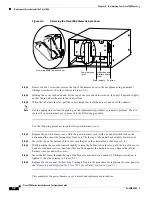
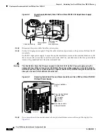
Figure 5-2
Replacing the Cisco 7505 Fan Tray
When you view the chassis from the noninterface processor end, the fan tray is on the far right. See
Figure 5-2
.
A cutout in the front of the tray provides a handle for pulling the tray out of the chassis. An M4 Phillips
screw anchors a tab on the bottom edge of the tray to the interior chassis frame, just below the right
power supply ear.
When the fan tray is fully inserted in the chassis, an edge connector on the fan control board slides into
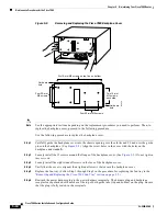
the backplane electrical connector. The bottom of the tray is a metal runner that guides the tray along a
metal track on the chassis floor. (See
Figure 5-3
.) Also, a bracket on the chassis ceiling helps guide the
tray into the chassis.
Removing/replacing
fan tray
H9726