5-8
Cisco 7500 Series Installation and Configuration Guide
OL-5008-03 B0
Chapter 5 Maintaining Your Cisco 7505 Router
Maintenance Procedures for the Cisco 7505
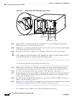
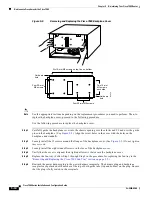
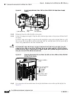
Figure 5-4
Removing the Cisco 7505 Power Harness Cover
Step 3
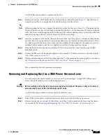
Remove the M3 screw that secures the top of the harness cover to the backplane using a number 1
Phillips screwdriver. (See the cutaway in
Figure 5-4
.)
Step 4
Holding the cover with one hand, tilt the top of the cover back toward you, then pull it upward slightly
so that the tab clears the slot in the chassis floor.
Step 5
When the tab clears the slot, pull the cover straight back off the harness and out of the chassis.
Note
See the appropriate sections depending on the replacement procedures you need to perform. Then, to
replace the power harness cover, proceed to the following procedure.
Use the following procedure to replace the power harness cover:
Step 1
Replace the power harness cover. Hold the power harness cover with one hand, with the tab on the
bottom and the open side facing away from you. Tilt the top of the panel back slightly (toward you).
Step 2
Insert the tab on the bottom of the cover into the slot in the chassis floor. (See
Figure 5-4
.)
Step 3
While pushing the cover downward slightly to keep the bottom tab in the slot, push the top of the cover
back over the harness wires until the sides are flush against the backplane cover. Ensure that all the
harness wires are under the cover.
Step 4
Insert the M3 screw through the top of the harness cover, and use a number 1 Phillips screwdriver to
tighten it. (See the cutaway in
Figure 5-4
.)
Step 5
Replace the cover panel. (Follow Step 1 through Step 4 in the procedure for replacing the cover panel in
the
“Removing and Replacing the Cisco 7505 Cover Panel” section on page 5-3
.)
This completes the power harness cover removal and replacement procedures.
Power harness
cover
Arbiter/chassis
interface board
cover
Power supply
Fan tray
Removing power harness cover
H2867


