


6-5
Cisco 7500 Series Installation and Configuration Guide
OL-5008-03 B0
Chapter 6 Maintaining Your Cisco 7507 and Cisco 7507-MX Router
Maintenance Procedures for the Cisco 7507 and Cisco 7507-MX
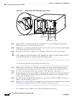
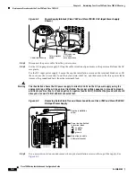
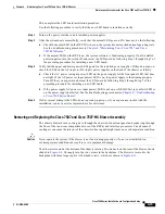
Figure 6-3
Power Supply Captive Installation Screw (Cisco 7507 and Cisco 7507-MX AC-Input
Power Supply Shown)
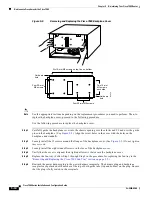
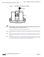
Step 6
Grasp the power supply handle with one hand and place your other hand underneath to support the
bottom of the power supply as shown in
Figure 6-4
.
Warning
Keep hands and fingers out of the power supply bays. High voltage is present on the power backplane
when the system is operating.
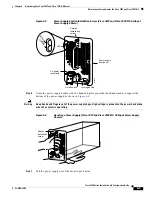
Figure 6-4
Handling a Power Supply (Cisco 7507 and Cisco 7507-MX AC-Input Power Supply
Shown)
Step 7
Pull the power supply out of the bay and put it aside.
I
O
DC
F
AIL
AC
P
OW
ER
Power supply
front panel
On/off switch
AC power
receptacle
LEDs
Captive
installation
screw
Locking device
H1314a
DC FAIL
AC POWER
I
0
DC
FA
IL
AC
PO
W
ER
H1356a
Captive
installation
screw