Installing Your Router
3-9
Connecting the Power Supply
Warning
This product relies on the building’s installation for short-circuit
(overcurrent) protection. Ensure that a fuse or circuit breaker no larger than
120 VAC, 15A U.S. (240 VAC, 16A international) is used on the phase conductors
(all current-carrying conductors).
Warning
This equipment is intended to be grounded. Ensure that the host is
connected to earth ground during normal use.
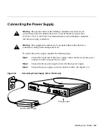
To connect the power supply, complete the following steps:
Step 1
Connect the round end of the power supply cable to the black circular power
connector on the rear panel of your router.
Step 2
Connect the black power supply cord to the black power supply.
Step 3
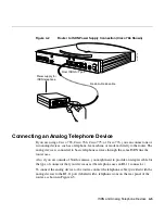
Connect the power supply cord to an electrical outlet. (See Figure 3-5.)
Figure 3-5
Connecting Power Supply (Cisco 765 shown)
Desktop power supply
DC power input
H5065
CONFIG
+5V ---1.5A +/-5%
-30V--- 0.2A +/-25%
S
0
ISDN S/T
Link
NODE
HUB
10BASET
Summary of Contents for 700 series
Page 8: ...Cisco 700 Series Router Installation Guide viii ...
Page 36: ...Where To Go From Here Cisco 700 Series Router Installation Guide 2 6 ...
Page 62: ...Where To Go From Here Cisco 700 Series Router Installation Guide 4 14 ...
Page 80: ...HUB NODE Switch Cisco 700 Series Router Installation Guide 6 6 ...
Page 96: ...Cisco 700 Series Router Installation Guide Loading a Configuration B 10 ...
Page 110: ...Cisco 700 Series Router Installation Guide Router Configuration Requirements C 14 ...

