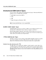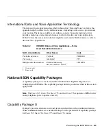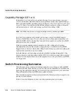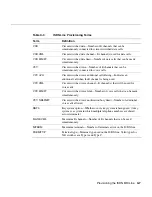
Cisco 700 Series Router Installation Guide
Index
4
F
fast busy
4-1
fee pulse mode
1-5
flash key
4-7
Flash memory
5-2, A-1
flexible calling
C-6
flow control
B-2
four-wire network
6-4
framing
B-7
front panel
1-10
H
hardware flow control
B-3
HDLC
5-2
HUB/NODE switch
5-5
settings
3-1, A-2
Hyperterminal
B-1
I
IE
6-2
IEEE 802.1d MIB standard
1-8
inband timeout violation error
5-6
INS ISDN lines in Japan
4-10
Integrated Network Service
4-10
Integrated Service Digital Network
See ISDN BRI
interface chip error
5-2
interfaces
1-13
internal tones
4-11
Internet Protocol Control Protocol (IPCP)
See IPCP
IOS software
B-1
IP
address assignment through IPCP
1-5
address, definition
6-2
filtering
1-7
IPCP
1-5, 1-8, 1-9
ISDN BRI
1-1, C-1
cause values
5-6 to 5-12
channel service
6-3
configuration requirements
C-10 to C-13
connecting lines
3-3
data and voice
C-1
definition
6-2
Europe
4-11
internal tones, analog telephone
4-11
provisioning
C-1 to C-4
service provider
5-3
setting the switch type
5-3
stack revision
1TR6 2.10
C-4
NET3 2.10
C-4
switch provisioning
C-6 to C-10
switch types
1TR6
4-11, C-4
DMS-100
C-3
EURO-ISDN BRI
C-4
NET3
4-11
NI1
C-3
telephone, connecting to ISDN line
4-1
ISDN telephone
analog telephone
4-5
digital telephone
4-2
number
5-6
J
Japan
dialing instructions
4-10
disabling end-of-call function
4-11
disabling pound (#) key
4-11
Summary of Contents for 700 series
Page 8: ...Cisco 700 Series Router Installation Guide viii ...
Page 36: ...Where To Go From Here Cisco 700 Series Router Installation Guide 2 6 ...
Page 62: ...Where To Go From Here Cisco 700 Series Router Installation Guide 4 14 ...
Page 80: ...HUB NODE Switch Cisco 700 Series Router Installation Guide 6 6 ...
Page 96: ...Cisco 700 Series Router Installation Guide Loading a Configuration B 10 ...
Page 110: ...Cisco 700 Series Router Installation Guide Router Configuration Requirements C 14 ...

