Overview
1-13
Rear Panels
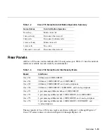
All Cisco 700 series routers include a
DB-9F configuration port.
Table 1-3 lists the network
interfaces available on each router by model number.
l
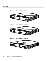
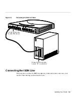
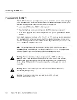
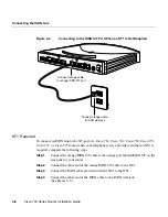
The rear panels of Cisco 760 series routers are shown in Figure 1-4 through Figure 1-7.
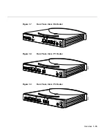
Cisco 770 series routers are shown in Figure 1-8 through Figure 1-11.
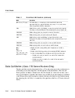
Table 1-2
Cisco 770 Series Data Call Button Operation Summary
Current Status
Data Call Button Operation
No call up
Make a data call
1 data call only
Disconnect the data call
2 data calls
Disconnect both data calls
1 voice call only
Make a data call
2 voice calls
No action
1 data and 1 voice call
Disconnect the data call
Table 1-3
Cisco 700 Series Router Interfaces by Mode
Model
Interfaces
Cisco 761 1
Ethernet
and 1 ISDN BRI S/T
Cisco 762
1 Ethernet, 1 ISDN BRI S/T, and 1 ISDN BRI U
Cisco 765
1 Ethernet, 1 ISDN BRI S/T, and 2 analog telephone
Cisco 766
1 Ethernet, 1 ISDN BRI S/T, 1 ISDN BRI U, and 2 analog telephone
Cisco 771
4-port unmanaged Ethernet hub and 1 ISDN BRI S/T
Cisco 772
4-port unmanaged Ethernet hub, 1 ISDN BRI S/T, and 1 ISDN BRI U
Cisco 775
4-port unmanaged Ethernet hub, 1 ISDN BRI S/T, and 2 analog telephone
Cisco 776
4-port unmanaged Ethernet hub, 1 ISDN BRI S/T, 1 ISDN BRI U, and
2 analog telephone
Summary of Contents for 700 series
Page 8: ...Cisco 700 Series Router Installation Guide viii ...
Page 36: ...Where To Go From Here Cisco 700 Series Router Installation Guide 2 6 ...
Page 62: ...Where To Go From Here Cisco 700 Series Router Installation Guide 4 14 ...
Page 80: ...HUB NODE Switch Cisco 700 Series Router Installation Guide 6 6 ...
Page 96: ...Cisco 700 Series Router Installation Guide Loading a Configuration B 10 ...
Page 110: ...Cisco 700 Series Router Installation Guide Router Configuration Requirements C 14 ...

