Cisco 700 Series Router Installation Guide
Establishing a Terminal Connection
B-2
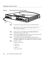
Figure B-1
Console Cable Connection (Cisco 766 Shown)
Step 2
Connect the other end of the console cable to the ASCII terminal or PC.
Note
The router is a data communications equipment (DCE) device. A
crossover cable is not required.
Step 3
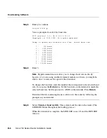
Start HyperTerminal. Click
Start
>
Accessories
>
HyperTerminal
. The
Connection Description window displays.
Step 4
Enter a name in the
Name
field of the Connection Description window. When
you click
OK
, the Phone Number window displays.
Step 5
Select the COM port from the
Connect using
list to which the router is
connected. For example, if the router is connected to the COM2 port of your PC,
select
Direct to COM2
. When you click
OK
, the Port Settings window displays.
Step 6
Set the port as follows:
•
Bits per second = 9600
•
Data bits = 8
•
Parity = None
•
Stop bits = 1
•
Flow control = None
CONFIG
+5V ---1.5A +/-5%
-30V--- 0.2A +/-25%
S
0
NT-1
ISDN U
ISDN S/T
Link
NODE
HUB
10BASET
Console
cable
H5063
Summary of Contents for 700 series
Page 8: ...Cisco 700 Series Router Installation Guide viii ...
Page 36: ...Where To Go From Here Cisco 700 Series Router Installation Guide 2 6 ...
Page 62: ...Where To Go From Here Cisco 700 Series Router Installation Guide 4 14 ...
Page 80: ...HUB NODE Switch Cisco 700 Series Router Installation Guide 6 6 ...
Page 96: ...Cisco 700 Series Router Installation Guide Loading a Configuration B 10 ...
Page 110: ...Cisco 700 Series Router Installation Guide Router Configuration Requirements C 14 ...

