


5-5
Cisco Wide Area Virtualization Engine 594 and 694 Hardware Installation Guide
OL-24619-02
Chapter 5 WAVE Interface Modules
Ports and LED Indicators
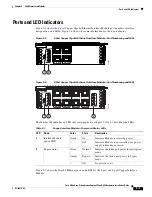
Ports and LED Indicators
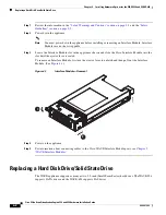
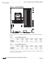
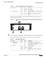
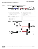
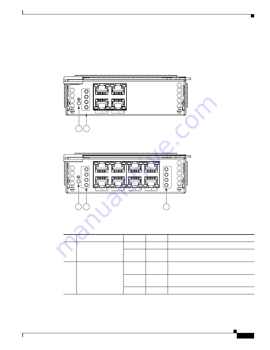
Figure 5-5
shows the 4-port Copper Gigabit Ethernet Interface Module port numbers, interface
designations, and LEDs.
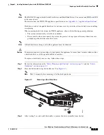
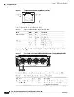
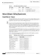
Figure 5-6
shows the same information for the 8-port adapter.
Figure 5-5
4-Port Copper Gigabit Ethernet Interface Module—Port Numbering and LEDs
Figure 5-6
8-Port Copper Gigabit Ethernet Interface Module—Port Numbering and LEDs
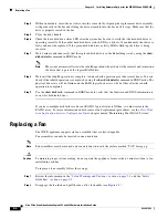
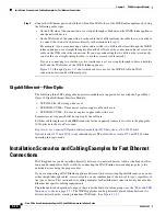
The Interface Module has an LED that corresponds to each port.
Table 5-1
describes the LEDs.
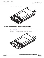
Figure 5-7
shows the Gigabit Ethernet ports and LEDs for the 4-port and 8-port Copper Interface
Module.
24654
8
4 PORT BYPASS
0
1
2
3
Status
GE 0/1
GE 2/3
1
2
GE 0/1
GE 2/3
GE 4/5
GE 6/7
8 Port GE
Copper Inline
0
1
2
3
Status
0
1
2
3
Status
24654
8
1
2
2
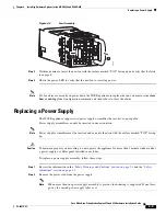
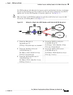
Table 5-1
Copper Interface Module—Power and Status LEDs
LED
Name
Color
State
Description
1
Interface Module
power LED
Green
On
Interface Module is receiving power.
—
Off
Interface Module is not installed or a power
supply failure has occurred.
2
Bypass status
Green
Normal
Indicates the inline port pair is in interception
mode.
Amber
Bypass
Indicates the inline port pair is in bypass
mode.
—
Off
No activity exists.