


1-4
Cisco Wide Area Virtualization Engine 594 and 694 Hardware Installation Guide
OL-24619-02
Chapter 1 Introducing the Cisco Wide Area Virtualization Engine 594 and 694
Hardware Features
Back Panel Components and LEDs
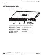
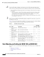
Figure 1-3
shows the back panel components.
Note
To monitor the boot process in normal operation, use a console port.
Figure 1-3
Back Panel Components
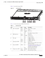
Figure 1-4
shows the back panel LEDs.
Figure 1-4
Back Panel LEDs
Table 1-2
describes the back panel LEDs and their functions.
1
Power supply 1
5
Fan 4
2
Power supply 0
6
Fan 3
3
Fan 6
7
Fan 2
4
Fan 5
8
Fan 1
1
2
3
4
5
6
7
8
1
2
3
4
5
6
7
8
Table 1-2
Back Panel LEDs
LED
Color
State
Description
1, 2
Power supply status
—
Off
No AC power to all power supplies.
Red
Blinking
No AC power to this power supply.
Green
Blinking
AC power is present, only standby output on.
Green
On
Power supply DC outputs on and OK.
Red
On
Power supply failure. Refer to the
“Troubleshooting the System Hardware”
chapter for more information.