


Server Chassis
3. Insert the power supply to
the chassis with the power
supply fan facing down.
Use the mounting screws to
secure the position.
= Power Supply Installation =
4. Please follow M/B
Installation Guide to
connect power cables
to M/B.
= Motherboard Installation =
5. Connect all cables to M/B. (Included USB,
HDD LED, HD Audio, Power Switch, Power
LED, Reset Switch, Intrusion switch).
= Front I/O Wires Installation =
USB Header
HD AUDIO Header
(white)
(Orange)
-
+
(white)
(Brown)
-
+
(white)
(Red)
-
+
(white)
(Blue)
-
+
(white)
(Blue)
-
+
VCC2
(RED)
VCC1
(RED)
2
1
D2-
(WHITE)
D1-
(WHITE)
4
3
D2+
(GREEN)
D1+
(GREEN)
6
5
GND
(BLACK)
GND
(BLACK)
8
7
KEY
NC
9
10
MIC
(BROWN)
AUD_GND
(BLACK)
2
1
MIC_BIAS
(ORANGE)
AUD_GND
(BLACK)
4
3
FP_OUT_R
(GREEN)
FP_RET_R
(YELLOW)
6
5
AUD_VCC
(RED)
KEY
8
FP_OUT_L
(PURPLE / WHITE)
FP_RET_L
(BLUE)
9
Intrusion Switch Header
AC’97 Audio Header
10
MIC
(BROWN)
AUD_GND
(BLACK)
2
1
MIC_BIAS
(ORANGE)
AUD_GND
(BLACK)
4
3
FP_OUT_R
(GREEN)
FP_RET_R
(YELLOW)
6
5
AUD_VCC
(RED)
KEY
8
FP_OUT_L
(PURPLE / WHITE)
FP_RET_L
(BLUE)
9
C
NC
NO
When the side cover
is opened.
When the side cover
is closed.
C
NC
NO
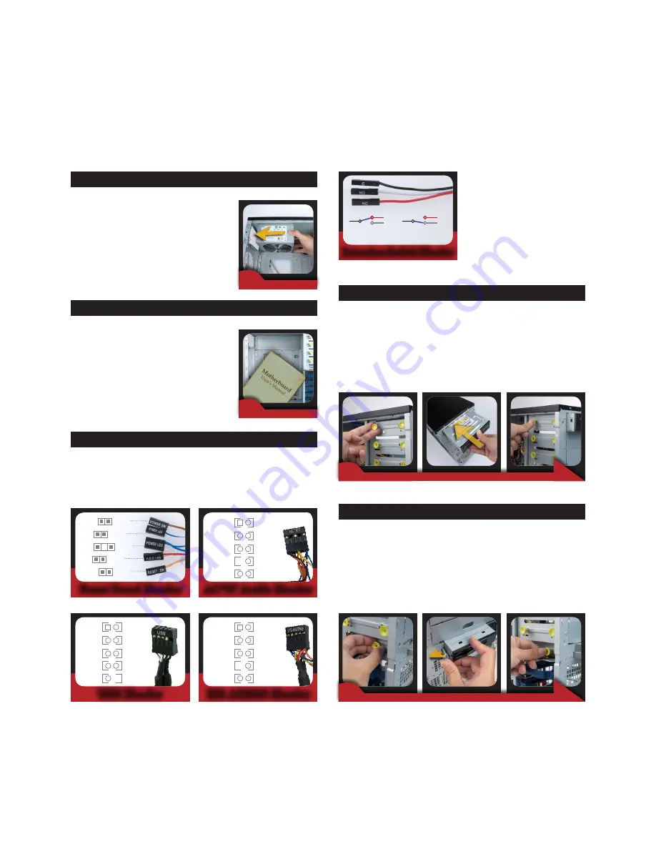
6. Pull the “ODD Secure Clips”, put the
5.25”optical drive in and then press the
clips.Refer from the M/B Quick Reference
and Manual to connect the signal cable and
power cable.
= 5.25 ODD Installation =
7. Pull the FDD Secure Clips, push the
3.5"
component
Lock to the left, insert the
3.5"
component
and press
down the clips. Refer
from the M/B Guideline
to connect the signal
cable, and then connect
the output power
cable.
= 3.5”
External
Installation =
Front Panel Header
Summary of Contents for Kronos 600 X79-KA SERIES
Page 1: ...User Guide Kronos 600 Workstation X79 KA XXXXX XX XXX...
Page 8: ...CIARA Kronos 600 workstation X79 KA XXXXX XX XXX 8...
Page 36: ...CIARA Kronos 600 workstation X79 KA XXXXX XX XXX 36 NOTES...
Page 43: ...P9X79 WS Motherboard...
Page 58: ...16...
Page 107: ...ASUS P9X79 WS 2 37 5 6 Triangle mark 7 8 B A 9 B A...
Page 109: ...ASUS P9X79 WS 2 39 2 3 4 DIMM installation 1 2 3 To remove aDIMM B A...
Page 111: ...ASUS P9X79 WS 2 41 3 DO NOT overtighten the screws Doing so can damage the motherboard...
Page 112: ...2 42 Chapter 2 Hardware information 2 3 6 ATX Power connection 1 2 OR...
Page 113: ...ASUS P9X79 WS 2 43 2 3 7 SATAdevice connection 1 OR 2...
Page 122: ...2 52 Chapter 2 Hardwareinformation...
Page 226: ...5 14 Chapter 5 rv JltipleGPUtechnology support...


