increase vehicle emissions and deteriorate engine
performance, driveability and fuel economy.
The catalyst monitor uses dual oxygen sensors
(O2S’s) to monitor the efficiency of the converter. The
dual O2Ss strategy is based on the fact that as a cat-
alyst deteriorates, its oxygen storage capacity and its
efficiency are both reduced. By monitoring the oxy-
gen storage capacity of a catalyst, its efficiency can
be indirectly calculated. The upstream O2S is used to
detect the amount of oxygen in the exhaust gas
before the gas enters the catalytic converter. The
PCM calculates the A/F mixture from the output of
the O2S. A low voltage indicates high oxygen content
(lean mixture). A high voltage indicates a low content
of oxygen (rich mixture).
When the upstream O2S detects a lean condition,
there is an abundance of oxygen in the exhaust gas.
A functioning converter would store this oxygen so it
can use it for the oxidation of HC and CO. As the
converter absorbs the oxygen, there will be a lack of
oxygen downstream of the converter. The output of
the downstraem O2S will indicate limited activity in
this condition.
As the converter loses the ability to store oxygen,
the condition can be detected from the behavior of
the downstream O2S. When the efficiency drops, no
chemical reaction takes place. This means the con-
centration of oxygen will be the same downstream as
upstream. The output voltage of the downstream
O2S copies the voltage of the upstream sensor. The
only difference is a time lag (seen by the PCM)
between the switching of the O2S’s.
To monitor the system, the number of lean-to-rich
switches of upstream and downstream O2S’s is
counted.
The
ratio
of
downstream
switches
to
upstream switches is used to determine whether the
catalyst is operating properly. An effective catalyst
will have fewer downstream switches than it has
upstream switches i.e., a ratio closer to zero. For a
totally ineffective catalyst, this ratio will be one-to-
one, indicating that no oxidation occurs in the device.
The system must be monitored so that when cata-
lyst efficiency deteriorates and exhaust emissions
increase to over the legal limit, the MIL (check
engine lamp) will be illuminated.
DTC 31—HEX A0, A1, B7, and B8—LEAK
DETECTION PUMP MONITOR
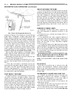
The leak detection assembly incorporates two pri-
mary functions: it must detect a leak in the evapora-
tive system and seal the evaporative system so the
leak detection test can be run.
The primary components within the assembly are:
A three port solenoid that activates both of the func-
tions listed above; a pump which contains a switch,
two check valves and a spring/diaphragm, a canister
vent valve (CVV) seal which contains a spring loaded
vent seal valve.
Immediately after a cold start, between predeter-
mined temperature thresholds limits, the three port
solenoid is briefly energized. This initializes the
pump by drawing air into the pump cavity and also
closes the vent seal. During non test conditions the
vent seal is held open by the pump diaphragm
assembly which pushes it open at the full travel posi-
tion. The vent seal will remain closed while the
pump is cycling due to the reed switch triggering of
the three port solenoid that prevents the diaphragm
assembly from reaching full travel. After the brief
initialization period, the solenoid is de-energized
allowing atmospheric pressure to enter the pump
cavity, thus permitting the spring to drive the dia-
phragm which forces air out of the pump cavity and
into the vent system. When the solenoid is energized
and de energized, the cycle is repeated creating flow
in typical diaphragm pump fashion. The pump is con-
trolled in 2 modes:
Pump Mode: The pump is cycled at a fixed rate to
achieve a rapid pressure build in order to shorten the
overall test length.
Test Mode: The solenoid is energized with a fixed
duration pulse. Subsequent fixed pulses occur when
the diaphragm reaches the Switch closure point.
The spring in the pump is set so that the system
will achieve an equalized pressure of about 7.5” H20.
The cycle rate of pump strokes is quite rapid as the
system begins to pump up to this pressure. As the
pressure increases, the cycle rate starts to drop off. If
there is no leak in the system, the pump would even-
tually stop pumping at the equalized pressure. If
there is a leak, it will continue to pump at a rate rep-
resentative of the flow characteristic of the size of the
leak. From this information we can determine if the
leak is larger than the required detection limit (cur-
rently set at .040” orifice by CARB). If a leak is
revealed during the leak test portion of the test, the
test is terminated at the end of the test mode and no
further system checks will be performed.
After passing the leak detection phase of the test,
system pressure is maintained by turning on the
LDP’s solenoid until the purge system is activated.
Purge activation in effect creates a leak. The cycle
rate is again interrogated and when it increases due
to the flow through the purge system, the leak check
portion of the diagnostic is complete.
The canister vent valve will unseal the system
after completion of the test sequence as the pump
diaphragm assembly moves to the full travel position.
Evaporative system functionality will be verified by
using the stricter evap purge flow monitor. At an
appropriate warm idle the LDP will be energized to
seal the canister vent. The purge flow will be clocked
JA
EMISSION CONTROL SYSTEMS
25 - 9
DESCRIPTION AND OPERATION (Continued)
Summary of Contents for Stratus LHD 1997
Page 11: ......
Page 79: ......
Page 193: ......
Page 205: ......
Page 239: ......
Page 273: ......
Page 293: ......
Page 296: ...Charging System Schematic Typical JA CHARGING SYSTEM 8C 3 DIAGNOSIS AND TESTING Continued ...
Page 307: ......
Page 309: ......
Page 343: ...8D 34 IGNITION SYSTEM JA SPECIFICATIONS Continued ...
Page 377: ...8D 34 IGNITION SYSTEM JA SPECIFICATIONS Continued ...
Page 379: ......
Page 381: ......
Page 395: ......
Page 399: ......
Page 421: ......
Page 469: ......
Page 509: ......
Page 515: ......
Page 519: ......
Page 521: ......
Page 533: ......
Page 537: ......
Page 539: ......
Page 540: ......
Page 541: ......
Page 542: ......
Page 543: ......
Page 544: ......
Page 545: ......
Page 546: ......
Page 547: ......
Page 548: ......
Page 549: ......
Page 550: ......
Page 551: ......
Page 552: ......
Page 553: ......
Page 554: ......
Page 557: ......
Page 558: ......
Page 559: ......
Page 560: ......
Page 561: ......
Page 562: ......
Page 563: ......
Page 564: ......
Page 565: ......
Page 566: ......
Page 567: ......
Page 568: ......
Page 569: ......
Page 570: ......
Page 571: ......
Page 572: ......
Page 573: ......
Page 575: ......
Page 577: ......
Page 578: ......
Page 579: ......
Page 580: ......
Page 581: ......
Page 582: ......
Page 583: ......
Page 585: ......
Page 587: ......
Page 589: ......
Page 591: ......
Page 593: ......
Page 595: ......
Page 596: ......
Page 597: ......
Page 598: ......
Page 599: ......
Page 600: ......
Page 601: ......
Page 602: ......
Page 603: ......
Page 604: ......
Page 605: ......
Page 606: ......
Page 607: ......
Page 608: ......
Page 609: ......
Page 610: ......
Page 611: ......
Page 612: ......
Page 621: ......
Page 622: ......
Page 623: ......
Page 624: ......
Page 625: ......
Page 626: ......
Page 627: ......
Page 631: ......
Page 633: ......
Page 634: ......
Page 637: ......
Page 638: ......
Page 639: ......
Page 640: ......
Page 641: ......
Page 645: ......
Page 646: ......
Page 647: ......
Page 648: ......
Page 649: ......
Page 650: ......
Page 651: ......
Page 657: ......
Page 659: ......
Page 661: ......
Page 662: ......
Page 663: ......
Page 667: ......
Page 668: ......
Page 671: ......
Page 672: ......
Page 673: ......
Page 677: ......
Page 678: ......
Page 679: ......
Page 680: ......
Page 681: ......
Page 682: ......
Page 683: ......
Page 684: ......
Page 685: ......
Page 686: ......
Page 689: ......
Page 691: ......
Page 693: ......
Page 695: ......
Page 696: ......
Page 699: ......
Page 701: ......
Page 703: ......
Page 705: ......
Page 706: ......
Page 707: ......
Page 711: ......
Page 712: ......
Page 715: ......
Page 716: ......
Page 719: ......
Page 721: ......
Page 722: ......
Page 725: ......
Page 727: ......
Page 728: ......
Page 731: ......
Page 733: ......
Page 734: ......
Page 737: ......
Page 739: ......
Page 741: ......
Page 742: ......
Page 745: ......
Page 747: ......
Page 749: ......
Page 751: ......
Page 753: ......
Page 754: ......
Page 755: ......
Page 756: ......
Page 757: ......
Page 758: ......
Page 759: ......
Page 763: ......
Page 764: ......
Page 765: ......
Page 766: ......
Page 767: ......
Page 768: ......
Page 769: ......
Page 770: ......
Page 771: ......
Page 772: ......
Page 773: ......
Page 774: ......
Page 775: ......
Page 776: ......
Page 777: ......
Page 778: ......
Page 779: ......
Page 780: ......
Page 781: ......
Page 782: ......
Page 783: ......
Page 784: ......
Page 785: ......
Page 786: ......
Page 787: ......
Page 788: ......
Page 789: ......
Page 790: ......
Page 791: ......
Page 792: ......
Page 793: ......
Page 794: ......
Page 795: ......
Page 796: ......
Page 797: ......
Page 798: ......
Page 799: ......
Page 800: ......
Page 801: ......
Page 802: ......
Page 803: ......
Page 804: ......
Page 805: ......
Page 806: ......
Page 807: ......
Page 835: ...Fig 7 Body Splices 8W 95 6 8W 95 SPLICE LOCATIONS JA DESCRIPTION AND OPERATION Continued ...
Page 837: ......
Page 975: ...Adapter 6887 Camshaft Seal Installer 6863 9 138 2 5L ENGINE JA SPECIAL TOOLS Continued ...
Page 1001: ...13 6 BUMPERS AND FRAME JA SPECIFICATIONS Continued ...
Page 1065: ...Fuel Line Adapter 1 4 14 64 FUEL SYSTEM JA SPECIAL TOOLS Continued ...
Page 1071: ......
Page 1236: ...41TE TRANSAXLE HYDRAULIC SCHEMATIC JA TRANSAXLE 21 105 SCHEMATICS AND DIAGRAMS Continued ...
Page 1237: ...41TE TRANSAXLE HYDRAULIC SCHEMATIC 21 106 TRANSAXLE JA SCHEMATICS AND DIAGRAMS Continued ...
Page 1238: ...41TE TRANSAXLE HYDRAULIC SCHEMATIC JA TRANSAXLE 21 107 SCHEMATICS AND DIAGRAMS Continued ...
Page 1239: ...41TE TRANSAXLE HYDRAULIC SCHEMATIC 21 108 TRANSAXLE JA SCHEMATICS AND DIAGRAMS Continued ...
Page 1240: ...41TE TRANSAXLE HYDRAULIC SCHEMATIC JA TRANSAXLE 21 109 SCHEMATICS AND DIAGRAMS Continued ...
Page 1241: ...41TE TRANSAXLE HYDRAULIC SCHEMATIC 21 110 TRANSAXLE JA SCHEMATICS AND DIAGRAMS Continued ...
Page 1242: ...41TE TRANSAXLE HYDRAULIC SCHEMATIC JA TRANSAXLE 21 111 SCHEMATICS AND DIAGRAMS Continued ...
Page 1243: ...41TE TRANSAXLE HYDRAULIC SCHEMATIC 21 112 TRANSAXLE JA SCHEMATICS AND DIAGRAMS Continued ...
Page 1244: ...41TE TRANSAXLE HYDRAULIC SCHEMATIC JA TRANSAXLE 21 113 SCHEMATICS AND DIAGRAMS Continued ...
Page 1245: ...41TE TRANSAXLE HYDRAULIC SCHEMATIC 21 114 TRANSAXLE JA SCHEMATICS AND DIAGRAMS Continued ...
Page 1246: ...41TE TRANSAXLE HYDRAULIC SCHEMATIC JA TRANSAXLE 21 115 SCHEMATICS AND DIAGRAMS Continued ...
Page 1247: ...41TE TRANSAXLE HYDRAULIC SCHEMATIC 21 116 TRANSAXLE JA SCHEMATICS AND DIAGRAMS Continued ...
Page 1248: ...41TE TRANSAXLE HYDRAULICSCHEMATIC JA TRANSAXLE 21 117 SCHEMATICS AND DIAGRAMS Continued ...
Page 1271: ......
Page 1287: ...SPECIFICATIONS SUNROOF COMPONENTS 23 16 BODY JA ...
Page 1318: ...SPECIAL TOOLS BODY REMOVER MOLDINGS C 4829 STICK TRIM C4755 JA BODY 23 47 ...
Page 1319: ......
Page 1321: ...Fig 1 Floor Console 23 2 BODY JA REMOVAL AND INSTALLATION Continued ...
Page 1359: ......
Page 1387: ......
Page 1401: ...FASTENER IDENTIFICATION 6 INTRODUCTION JA GENERAL INFORMATION Continued ...
Page 1404: ...METRIC CONVERSION JA INTRODUCTION 9 GENERAL INFORMATION Continued ...
Page 1512: ...41TE TRANSAXLE HYDRAULIC SCHEMATIC JA TRANSAXLE 21 105 SCHEMATICS AND DIAGRAMS Continued ...
Page 1513: ...41TE TRANSAXLE HYDRAULIC SCHEMATIC 21 106 TRANSAXLE JA SCHEMATICS AND DIAGRAMS Continued ...
Page 1514: ...41TE TRANSAXLE HYDRAULIC SCHEMATIC JA TRANSAXLE 21 107 SCHEMATICS AND DIAGRAMS Continued ...
Page 1515: ...41TE TRANSAXLE HYDRAULIC SCHEMATIC 21 108 TRANSAXLE JA SCHEMATICS AND DIAGRAMS Continued ...
Page 1516: ...41TE TRANSAXLE HYDRAULIC SCHEMATIC JA TRANSAXLE 21 109 SCHEMATICS AND DIAGRAMS Continued ...
Page 1517: ...41TE TRANSAXLE HYDRAULIC SCHEMATIC 21 110 TRANSAXLE JA SCHEMATICS AND DIAGRAMS Continued ...
Page 1518: ...41TE TRANSAXLE HYDRAULIC SCHEMATIC JA TRANSAXLE 21 111 SCHEMATICS AND DIAGRAMS Continued ...
Page 1519: ...41TE TRANSAXLE HYDRAULIC SCHEMATIC 21 112 TRANSAXLE JA SCHEMATICS AND DIAGRAMS Continued ...
Page 1520: ...41TE TRANSAXLE HYDRAULIC SCHEMATIC JA TRANSAXLE 21 113 SCHEMATICS AND DIAGRAMS Continued ...
Page 1521: ...41TE TRANSAXLE HYDRAULIC SCHEMATIC 21 114 TRANSAXLE JA SCHEMATICS AND DIAGRAMS Continued ...
Page 1522: ...41TE TRANSAXLE HYDRAULIC SCHEMATIC JA TRANSAXLE 21 115 SCHEMATICS AND DIAGRAMS Continued ...
Page 1523: ...41TE TRANSAXLE HYDRAULIC SCHEMATIC 21 116 TRANSAXLE JA SCHEMATICS AND DIAGRAMS Continued ...
Page 1524: ...41TE TRANSAXLE HYDRAULICSCHEMATIC JA TRANSAXLE 21 117 SCHEMATICS AND DIAGRAMS Continued ...


