


CAMSHAFT/HYDRAULIC LASH ADJUSTERS
A vertical hole at the number five bulkhead routes
pressurized oil through a restrictor up into the cylin-
der head. The rocker shafts route oil to the rocker
arms/hydraulic lash adjuster assemblies.
SPLASH LUBRICATION
Oil returning to the pan from pressurized compo-
nents supplies lubrication to the valve stems. Cylin-
der bores and wrist pins are splash lubricated from
directed slots on the connecting rod thrust collars.
ENGINE COMPONENTS
CYLINDER BLOCK AND BEDPLATE ASSEM-
BLY A partial open deck is used for cooling and
weight reduction with water pump molded into the
block. Nominal wall thickness is 4 mm. The bedplate
incorporates main bearing caps. Rear seal retainer is
integral with the block.
CRANKSHAFT A nodular cast iron crankshaft is
used. The engine has 5 main bearings, with number
3 flanged to control thrust. The 52 mm diameter
main and 48 mm diameter crank pin journals (all)
have undercut fillet radiuses that are deep rolled for
added strength. To optimize bearing loading 8 coun-
terweights are used. Hydrodynamic seals provide end
sealing,
where
the
crankshaft
exits
the
block.
Anaerobic gasket material is used for parting line
sealing. A sintered iron timing belt sprocket is
mounted on the crankshaft nose. This sprocket trans-
mits crankshaft movement, via timing belt to the
camshaft sprocket providing timed valve actuation.
PISTONS The SOHC Engine DOES NOT have
provision for a free wheeling valve train. Non free
wheeling valve train means, in the event of a broken
timing belt Pistons will contact the Valves. All
engines use pressed-in piston pins to attach forged
powdered metal connecting rods. The connecting rods
are a cracked cap design and are not repairable. Hex
head cap screw are used to provide alignment and
durability in the assembly. Pistons And Connecting
rods are serviced as an assembly.
PISTON RINGS The piston rings include a
molybdenum faced top ring for reliable compression
sealing and a taper faced intermediate ring for addi-
tional cylinder pressure control. Oil Control Ring
Package consist of 2 steel rails and a expander
spacer.
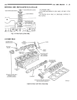
CYLINDER HEAD — SOHC It features a Single
Over Head Camshaft, four-valves per cylinder cross
flow design. The valves are arranged in two inline
banks, with the two intake per cylinder facing
toward the radiator. The exhaust valves facing
toward the dash panel. Rocker arm shafts mount
directly to the cylinder head. It incorporates powder
metal valve guides and seats. The hollow rocker arm
shafts supplies oil to the hydraulic lash adjusters,
camshaft and valve mechanisms.
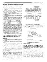
CAMSHAFT — SOHC The nodular iron camshaft
has five bearing journals and 3 cam lobes per cylin-
der. Provision for cam position sensor on the cam at
the rear of cylinder head which also acts as thrust
plate. A hydrodynamic oil seal is used for oil control
at the front of the camshaft.
VALVES — SOHC Four valves per cylinder are
actuated by roller rocker arms/hydraulic lash adjust-
ers assemblies which pivot on rocker arm shafts. All
valves have 6 mm diameter chrome plated valve
stems. The valve train has 33 mm (1.299 inch) diam-
eter intake valves and 28 mm (1.10 inch) diameter
exhaust valves. Viton rubber valve stem seals are
integral with spring seats. Valve springs, spring
retainers, and locks are conventional design.
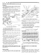
INTAKE MANIFOLD The intake manifold is a
molded plastic composition, attached to the cylinder
head with ten fasteners. This long branch design
enhances low and midrange torque.
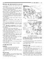
EXHAUST MANIFOLD The exhaust manifold is
made of nodular cast iron for strength and high tem-
peratures. Exhaust gasses exit through a machined,
articulated joint connection to the exhaust pipe.
PARTS REPLACED
If any of the following parts have been changed or
replaced:
•
Camshaft
•
Camshaft Position Sensor
•
Camshaft Position Sensor Target Magnet
•
Cylinder Block
•
Cylinder Head
•
Water Pump
•
Powertrain Control Module (PCM)
•
Timing belt and tensioner.
The camshaft and crankshaft timing relearn proce-
dure must be performed. Refer to Group 25, for pro-
cedure.
DIAGNOSIS AND TESTING
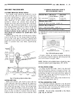
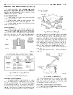
CHECKING ENGINE OIL PRESSURE
(1) Remove oil pressure switch and install gauge
assembly C-3292 with adaptor.
(2) Run engine until thermostat opens.
CAUTION:
If oil pressure is 0 at idle, Do Not per-
form the 3000 RPM test in the next step.
(3) Oil Pressure: Curb Idle 25 kPa (4 psi) mini-
mum 3000 RPM 170-550 kPa (25-80 psi).
(4) If oil pressure is 0 at idle. Shut off engine,
check for pressure relief valve stuck open, a clogged
oil pick-up screen or a damaged oil pick-up tube
O-ring.
9 - 14
2.0L SOHC ENGINE
JA
DESCRIPTION AND OPERATION (Continued)
Summary of Contents for Stratus LHD 1997
Page 11: ......
Page 79: ......
Page 193: ......
Page 205: ......
Page 239: ......
Page 273: ......
Page 293: ......
Page 296: ...Charging System Schematic Typical JA CHARGING SYSTEM 8C 3 DIAGNOSIS AND TESTING Continued ...
Page 307: ......
Page 309: ......
Page 343: ...8D 34 IGNITION SYSTEM JA SPECIFICATIONS Continued ...
Page 377: ...8D 34 IGNITION SYSTEM JA SPECIFICATIONS Continued ...
Page 379: ......
Page 381: ......
Page 395: ......
Page 399: ......
Page 421: ......
Page 469: ......
Page 509: ......
Page 515: ......
Page 519: ......
Page 521: ......
Page 533: ......
Page 537: ......
Page 539: ......
Page 540: ......
Page 541: ......
Page 542: ......
Page 543: ......
Page 544: ......
Page 545: ......
Page 546: ......
Page 547: ......
Page 548: ......
Page 549: ......
Page 550: ......
Page 551: ......
Page 552: ......
Page 553: ......
Page 554: ......
Page 557: ......
Page 558: ......
Page 559: ......
Page 560: ......
Page 561: ......
Page 562: ......
Page 563: ......
Page 564: ......
Page 565: ......
Page 566: ......
Page 567: ......
Page 568: ......
Page 569: ......
Page 570: ......
Page 571: ......
Page 572: ......
Page 573: ......
Page 575: ......
Page 577: ......
Page 578: ......
Page 579: ......
Page 580: ......
Page 581: ......
Page 582: ......
Page 583: ......
Page 585: ......
Page 587: ......
Page 589: ......
Page 591: ......
Page 593: ......
Page 595: ......
Page 596: ......
Page 597: ......
Page 598: ......
Page 599: ......
Page 600: ......
Page 601: ......
Page 602: ......
Page 603: ......
Page 604: ......
Page 605: ......
Page 606: ......
Page 607: ......
Page 608: ......
Page 609: ......
Page 610: ......
Page 611: ......
Page 612: ......
Page 621: ......
Page 622: ......
Page 623: ......
Page 624: ......
Page 625: ......
Page 626: ......
Page 627: ......
Page 631: ......
Page 633: ......
Page 634: ......
Page 637: ......
Page 638: ......
Page 639: ......
Page 640: ......
Page 641: ......
Page 645: ......
Page 646: ......
Page 647: ......
Page 648: ......
Page 649: ......
Page 650: ......
Page 651: ......
Page 657: ......
Page 659: ......
Page 661: ......
Page 662: ......
Page 663: ......
Page 667: ......
Page 668: ......
Page 671: ......
Page 672: ......
Page 673: ......
Page 677: ......
Page 678: ......
Page 679: ......
Page 680: ......
Page 681: ......
Page 682: ......
Page 683: ......
Page 684: ......
Page 685: ......
Page 686: ......
Page 689: ......
Page 691: ......
Page 693: ......
Page 695: ......
Page 696: ......
Page 699: ......
Page 701: ......
Page 703: ......
Page 705: ......
Page 706: ......
Page 707: ......
Page 711: ......
Page 712: ......
Page 715: ......
Page 716: ......
Page 719: ......
Page 721: ......
Page 722: ......
Page 725: ......
Page 727: ......
Page 728: ......
Page 731: ......
Page 733: ......
Page 734: ......
Page 737: ......
Page 739: ......
Page 741: ......
Page 742: ......
Page 745: ......
Page 747: ......
Page 749: ......
Page 751: ......
Page 753: ......
Page 754: ......
Page 755: ......
Page 756: ......
Page 757: ......
Page 758: ......
Page 759: ......
Page 763: ......
Page 764: ......
Page 765: ......
Page 766: ......
Page 767: ......
Page 768: ......
Page 769: ......
Page 770: ......
Page 771: ......
Page 772: ......
Page 773: ......
Page 774: ......
Page 775: ......
Page 776: ......
Page 777: ......
Page 778: ......
Page 779: ......
Page 780: ......
Page 781: ......
Page 782: ......
Page 783: ......
Page 784: ......
Page 785: ......
Page 786: ......
Page 787: ......
Page 788: ......
Page 789: ......
Page 790: ......
Page 791: ......
Page 792: ......
Page 793: ......
Page 794: ......
Page 795: ......
Page 796: ......
Page 797: ......
Page 798: ......
Page 799: ......
Page 800: ......
Page 801: ......
Page 802: ......
Page 803: ......
Page 804: ......
Page 805: ......
Page 806: ......
Page 807: ......
Page 835: ...Fig 7 Body Splices 8W 95 6 8W 95 SPLICE LOCATIONS JA DESCRIPTION AND OPERATION Continued ...
Page 837: ......
Page 975: ...Adapter 6887 Camshaft Seal Installer 6863 9 138 2 5L ENGINE JA SPECIAL TOOLS Continued ...
Page 1001: ...13 6 BUMPERS AND FRAME JA SPECIFICATIONS Continued ...
Page 1065: ...Fuel Line Adapter 1 4 14 64 FUEL SYSTEM JA SPECIAL TOOLS Continued ...
Page 1071: ......
Page 1236: ...41TE TRANSAXLE HYDRAULIC SCHEMATIC JA TRANSAXLE 21 105 SCHEMATICS AND DIAGRAMS Continued ...
Page 1237: ...41TE TRANSAXLE HYDRAULIC SCHEMATIC 21 106 TRANSAXLE JA SCHEMATICS AND DIAGRAMS Continued ...
Page 1238: ...41TE TRANSAXLE HYDRAULIC SCHEMATIC JA TRANSAXLE 21 107 SCHEMATICS AND DIAGRAMS Continued ...
Page 1239: ...41TE TRANSAXLE HYDRAULIC SCHEMATIC 21 108 TRANSAXLE JA SCHEMATICS AND DIAGRAMS Continued ...
Page 1240: ...41TE TRANSAXLE HYDRAULIC SCHEMATIC JA TRANSAXLE 21 109 SCHEMATICS AND DIAGRAMS Continued ...
Page 1241: ...41TE TRANSAXLE HYDRAULIC SCHEMATIC 21 110 TRANSAXLE JA SCHEMATICS AND DIAGRAMS Continued ...
Page 1242: ...41TE TRANSAXLE HYDRAULIC SCHEMATIC JA TRANSAXLE 21 111 SCHEMATICS AND DIAGRAMS Continued ...
Page 1243: ...41TE TRANSAXLE HYDRAULIC SCHEMATIC 21 112 TRANSAXLE JA SCHEMATICS AND DIAGRAMS Continued ...
Page 1244: ...41TE TRANSAXLE HYDRAULIC SCHEMATIC JA TRANSAXLE 21 113 SCHEMATICS AND DIAGRAMS Continued ...
Page 1245: ...41TE TRANSAXLE HYDRAULIC SCHEMATIC 21 114 TRANSAXLE JA SCHEMATICS AND DIAGRAMS Continued ...
Page 1246: ...41TE TRANSAXLE HYDRAULIC SCHEMATIC JA TRANSAXLE 21 115 SCHEMATICS AND DIAGRAMS Continued ...
Page 1247: ...41TE TRANSAXLE HYDRAULIC SCHEMATIC 21 116 TRANSAXLE JA SCHEMATICS AND DIAGRAMS Continued ...
Page 1248: ...41TE TRANSAXLE HYDRAULICSCHEMATIC JA TRANSAXLE 21 117 SCHEMATICS AND DIAGRAMS Continued ...
Page 1271: ......
Page 1287: ...SPECIFICATIONS SUNROOF COMPONENTS 23 16 BODY JA ...
Page 1318: ...SPECIAL TOOLS BODY REMOVER MOLDINGS C 4829 STICK TRIM C4755 JA BODY 23 47 ...
Page 1319: ......
Page 1321: ...Fig 1 Floor Console 23 2 BODY JA REMOVAL AND INSTALLATION Continued ...
Page 1359: ......
Page 1387: ......
Page 1401: ...FASTENER IDENTIFICATION 6 INTRODUCTION JA GENERAL INFORMATION Continued ...
Page 1404: ...METRIC CONVERSION JA INTRODUCTION 9 GENERAL INFORMATION Continued ...
Page 1512: ...41TE TRANSAXLE HYDRAULIC SCHEMATIC JA TRANSAXLE 21 105 SCHEMATICS AND DIAGRAMS Continued ...
Page 1513: ...41TE TRANSAXLE HYDRAULIC SCHEMATIC 21 106 TRANSAXLE JA SCHEMATICS AND DIAGRAMS Continued ...
Page 1514: ...41TE TRANSAXLE HYDRAULIC SCHEMATIC JA TRANSAXLE 21 107 SCHEMATICS AND DIAGRAMS Continued ...
Page 1515: ...41TE TRANSAXLE HYDRAULIC SCHEMATIC 21 108 TRANSAXLE JA SCHEMATICS AND DIAGRAMS Continued ...
Page 1516: ...41TE TRANSAXLE HYDRAULIC SCHEMATIC JA TRANSAXLE 21 109 SCHEMATICS AND DIAGRAMS Continued ...
Page 1517: ...41TE TRANSAXLE HYDRAULIC SCHEMATIC 21 110 TRANSAXLE JA SCHEMATICS AND DIAGRAMS Continued ...
Page 1518: ...41TE TRANSAXLE HYDRAULIC SCHEMATIC JA TRANSAXLE 21 111 SCHEMATICS AND DIAGRAMS Continued ...
Page 1519: ...41TE TRANSAXLE HYDRAULIC SCHEMATIC 21 112 TRANSAXLE JA SCHEMATICS AND DIAGRAMS Continued ...
Page 1520: ...41TE TRANSAXLE HYDRAULIC SCHEMATIC JA TRANSAXLE 21 113 SCHEMATICS AND DIAGRAMS Continued ...
Page 1521: ...41TE TRANSAXLE HYDRAULIC SCHEMATIC 21 114 TRANSAXLE JA SCHEMATICS AND DIAGRAMS Continued ...
Page 1522: ...41TE TRANSAXLE HYDRAULIC SCHEMATIC JA TRANSAXLE 21 115 SCHEMATICS AND DIAGRAMS Continued ...
Page 1523: ...41TE TRANSAXLE HYDRAULIC SCHEMATIC 21 116 TRANSAXLE JA SCHEMATICS AND DIAGRAMS Continued ...
Page 1524: ...41TE TRANSAXLE HYDRAULICSCHEMATIC JA TRANSAXLE 21 117 SCHEMATICS AND DIAGRAMS Continued ...