


8W-60 POWER WINDOWS
INDEX
page
page
DESCRIPTION AND OPERATION
HELPFUL INFORMATION . . . . . . . . . . . . . . . . . . . 5
POWER WINDOWS . . . . . . . . . . . . . . . . . . . . . . . 4
DESCRIPTION AND OPERATION
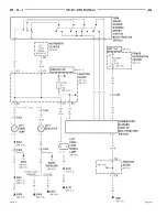
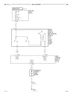
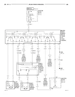
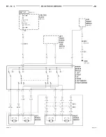
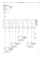
POWER WINDOWS
The power window system is powered by a 20 amp
circuit breaker located in the junction block cavity
19. This circuit breaker also feeds the power sun
roof.
The circuit breaker receives its feed from the igni-
tion switch on the A22 circuit. This circuit breaker is
HOT when the ignition switch is in the RUN position
only.
Circuit F21 is the feed circuit from the circuit
breaker to the power window switch. This circuit is
the feed for the entire system. The ground path for
the power windows is on the Z1 circuit and termi-
nates at the instrument panel left side cowl.
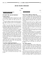
A LOCK-OUT feature is provided on the driver’s
door window switch. When this feature is engaged
the other windows in the system will not operate.
All of the door switches have a Light Emitting
Diode (L.E.D.) located inside of the switch. This diode
allows the operator to see the switch when it is dark.
The diodes are powered at all times, except when the
LOCK-OUT feature has been selected from the driv-
ers door switch. The L.E.D.’s located in the driver’s
door switch will always be illuminated regardless of
switch position.
Resistors and diodes internal to the switches are
used for the L.E.D’s. No attempt should be made to
repair these items. If the L.E.D. is not working, the
switch should be replaced.
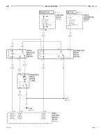
LEFT FRONT WINDOW OPERATION
When the operator selects window DOWN opera-
tion power is supplied on the F21 circuit through the
switch to circuit Q21. Circuit Q21 connects from the
switch to the power window motor. Ground for the
motor is supplied on the Q11 circuit back to the
switch. A bus bar, internal to the switch, connects the
Q11 circuit to the Z1 circuit. The Z1 circuit is termi-
nated at the instrument panel left side cowl.
For window UP operation the circuits are reversed.
Circuit Q11 is the feed, and circuit Q21 is the
ground.
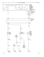
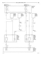
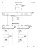
RIGHT FRONT WINDOW OPERATION
When the DRIVER selects window DOWN opera-
tion power is supplied on the F21 circuit through the
switch to circuit Q26. Circuit Q26 connects from the
drivers door switch to the right front door switch.
Power is passed through this switch to circuit Q22.
The Q22 circuit then connects to the right front win-
dow motor.
Ground for the window motor is supplied on the
Q12 circuit back to the right door switch. Circuity
internal to the switch then passes the ground to cir-
cuit Q16. Circuit Q16 connects from the right front
door switch to the master switch. A bus bar, internal
to the switch, connects the Q16 circuit to the Z1 cir-
cuit. The Z1 circuit is terminated at the instrument
panel left side cowl.
For window UP operation the circuits are reversed.
Circuits Q16 and Q12 are the feeds, and circuits Q22
and Q26 are the grounds.
If the switch is being operated from the PASSEN-
GER’S front door, and the operator is requesting win-
dow DOWN operation, power is supplied on the Q1
circuit
from
the
driver’s
master
switch
circuit
through the switch to the Q22 circuit.
Ground for the motor is supplied on the Q12 circuit
through the switch and back to the master switch on
circuit Q16. A bus bar, internal to the switch, con-
nects the Q16 circuit to the Z1 circuit. The Z1 circuit
is terminated at the instrument panel left side cowl.
For
window
UP
operation,
the
circuits
are
reversed. Circuit Q12 is the power and circuit Q22 is
the ground.
LEFT REAR WINDOW
When the DRIVER selects window DOWN opera-
tion power is supplied on the F21 circuit through the
switch to circuit Q27. Circuit Q27 connects from the
drivers door switch to the left rear door switch.
Power is passed through this switch to circuit Q23.
The Q23 circuit then connects to the left rear window
motor.
Ground for the window motor is supplied on the
Q13 circuit back to the left rear door switch. Circuity
internal to the switch then passes the ground to cir-
cuit Q17. Circuit Q17 connects from the left rear door
switch to the master switch. A bus bar, internal to
8W - 60 - 4
8W - 60 POWER WINDOWS
JA
Summary of Contents for Stratus LHD 1997
Page 11: ......
Page 79: ......
Page 193: ......
Page 205: ......
Page 239: ......
Page 273: ......
Page 293: ......
Page 296: ...Charging System Schematic Typical JA CHARGING SYSTEM 8C 3 DIAGNOSIS AND TESTING Continued ...
Page 307: ......
Page 309: ......
Page 343: ...8D 34 IGNITION SYSTEM JA SPECIFICATIONS Continued ...
Page 377: ...8D 34 IGNITION SYSTEM JA SPECIFICATIONS Continued ...
Page 379: ......
Page 381: ......
Page 395: ......
Page 399: ......
Page 421: ......
Page 469: ......
Page 509: ......
Page 515: ......
Page 519: ......
Page 521: ......
Page 533: ......
Page 537: ......
Page 539: ......
Page 540: ......
Page 541: ......
Page 542: ......
Page 543: ......
Page 544: ......
Page 545: ......
Page 546: ......
Page 547: ......
Page 548: ......
Page 549: ......
Page 550: ......
Page 551: ......
Page 552: ......
Page 553: ......
Page 554: ......
Page 557: ......
Page 558: ......
Page 559: ......
Page 560: ......
Page 561: ......
Page 562: ......
Page 563: ......
Page 564: ......
Page 565: ......
Page 566: ......
Page 567: ......
Page 568: ......
Page 569: ......
Page 570: ......
Page 571: ......
Page 572: ......
Page 573: ......
Page 575: ......
Page 577: ......
Page 578: ......
Page 579: ......
Page 580: ......
Page 581: ......
Page 582: ......
Page 583: ......
Page 585: ......
Page 587: ......
Page 589: ......
Page 591: ......
Page 593: ......
Page 595: ......
Page 596: ......
Page 597: ......
Page 598: ......
Page 599: ......
Page 600: ......
Page 601: ......
Page 602: ......
Page 603: ......
Page 604: ......
Page 605: ......
Page 606: ......
Page 607: ......
Page 608: ......
Page 609: ......
Page 610: ......
Page 611: ......
Page 612: ......
Page 621: ......
Page 622: ......
Page 623: ......
Page 624: ......
Page 625: ......
Page 626: ......
Page 627: ......
Page 631: ......
Page 633: ......
Page 634: ......
Page 637: ......
Page 638: ......
Page 639: ......
Page 640: ......
Page 641: ......
Page 645: ......
Page 646: ......
Page 647: ......
Page 648: ......
Page 649: ......
Page 650: ......
Page 651: ......
Page 657: ......
Page 659: ......
Page 661: ......
Page 662: ......
Page 663: ......
Page 667: ......
Page 668: ......
Page 671: ......
Page 672: ......
Page 673: ......
Page 677: ......
Page 678: ......
Page 679: ......
Page 680: ......
Page 681: ......
Page 682: ......
Page 683: ......
Page 684: ......
Page 685: ......
Page 686: ......
Page 689: ......
Page 691: ......
Page 693: ......
Page 695: ......
Page 696: ......
Page 699: ......
Page 701: ......
Page 703: ......
Page 705: ......
Page 706: ......
Page 707: ......
Page 711: ......
Page 712: ......
Page 715: ......
Page 716: ......
Page 719: ......
Page 721: ......
Page 722: ......
Page 725: ......
Page 727: ......
Page 728: ......
Page 731: ......
Page 733: ......
Page 734: ......
Page 737: ......
Page 739: ......
Page 741: ......
Page 742: ......
Page 745: ......
Page 747: ......
Page 749: ......
Page 751: ......
Page 753: ......
Page 754: ......
Page 755: ......
Page 756: ......
Page 757: ......
Page 758: ......
Page 759: ......
Page 763: ......
Page 764: ......
Page 765: ......
Page 766: ......
Page 767: ......
Page 768: ......
Page 769: ......
Page 770: ......
Page 771: ......
Page 772: ......
Page 773: ......
Page 774: ......
Page 775: ......
Page 776: ......
Page 777: ......
Page 778: ......
Page 779: ......
Page 780: ......
Page 781: ......
Page 782: ......
Page 783: ......
Page 784: ......
Page 785: ......
Page 786: ......
Page 787: ......
Page 788: ......
Page 789: ......
Page 790: ......
Page 791: ......
Page 792: ......
Page 793: ......
Page 794: ......
Page 795: ......
Page 796: ......
Page 797: ......
Page 798: ......
Page 799: ......
Page 800: ......
Page 801: ......
Page 802: ......
Page 803: ......
Page 804: ......
Page 805: ......
Page 806: ......
Page 807: ......
Page 835: ...Fig 7 Body Splices 8W 95 6 8W 95 SPLICE LOCATIONS JA DESCRIPTION AND OPERATION Continued ...
Page 837: ......
Page 975: ...Adapter 6887 Camshaft Seal Installer 6863 9 138 2 5L ENGINE JA SPECIAL TOOLS Continued ...
Page 1001: ...13 6 BUMPERS AND FRAME JA SPECIFICATIONS Continued ...
Page 1065: ...Fuel Line Adapter 1 4 14 64 FUEL SYSTEM JA SPECIAL TOOLS Continued ...
Page 1071: ......
Page 1236: ...41TE TRANSAXLE HYDRAULIC SCHEMATIC JA TRANSAXLE 21 105 SCHEMATICS AND DIAGRAMS Continued ...
Page 1237: ...41TE TRANSAXLE HYDRAULIC SCHEMATIC 21 106 TRANSAXLE JA SCHEMATICS AND DIAGRAMS Continued ...
Page 1238: ...41TE TRANSAXLE HYDRAULIC SCHEMATIC JA TRANSAXLE 21 107 SCHEMATICS AND DIAGRAMS Continued ...
Page 1239: ...41TE TRANSAXLE HYDRAULIC SCHEMATIC 21 108 TRANSAXLE JA SCHEMATICS AND DIAGRAMS Continued ...
Page 1240: ...41TE TRANSAXLE HYDRAULIC SCHEMATIC JA TRANSAXLE 21 109 SCHEMATICS AND DIAGRAMS Continued ...
Page 1241: ...41TE TRANSAXLE HYDRAULIC SCHEMATIC 21 110 TRANSAXLE JA SCHEMATICS AND DIAGRAMS Continued ...
Page 1242: ...41TE TRANSAXLE HYDRAULIC SCHEMATIC JA TRANSAXLE 21 111 SCHEMATICS AND DIAGRAMS Continued ...
Page 1243: ...41TE TRANSAXLE HYDRAULIC SCHEMATIC 21 112 TRANSAXLE JA SCHEMATICS AND DIAGRAMS Continued ...
Page 1244: ...41TE TRANSAXLE HYDRAULIC SCHEMATIC JA TRANSAXLE 21 113 SCHEMATICS AND DIAGRAMS Continued ...
Page 1245: ...41TE TRANSAXLE HYDRAULIC SCHEMATIC 21 114 TRANSAXLE JA SCHEMATICS AND DIAGRAMS Continued ...
Page 1246: ...41TE TRANSAXLE HYDRAULIC SCHEMATIC JA TRANSAXLE 21 115 SCHEMATICS AND DIAGRAMS Continued ...
Page 1247: ...41TE TRANSAXLE HYDRAULIC SCHEMATIC 21 116 TRANSAXLE JA SCHEMATICS AND DIAGRAMS Continued ...
Page 1248: ...41TE TRANSAXLE HYDRAULICSCHEMATIC JA TRANSAXLE 21 117 SCHEMATICS AND DIAGRAMS Continued ...
Page 1271: ......
Page 1287: ...SPECIFICATIONS SUNROOF COMPONENTS 23 16 BODY JA ...
Page 1318: ...SPECIAL TOOLS BODY REMOVER MOLDINGS C 4829 STICK TRIM C4755 JA BODY 23 47 ...
Page 1319: ......
Page 1321: ...Fig 1 Floor Console 23 2 BODY JA REMOVAL AND INSTALLATION Continued ...
Page 1359: ......
Page 1387: ......
Page 1401: ...FASTENER IDENTIFICATION 6 INTRODUCTION JA GENERAL INFORMATION Continued ...
Page 1404: ...METRIC CONVERSION JA INTRODUCTION 9 GENERAL INFORMATION Continued ...
Page 1512: ...41TE TRANSAXLE HYDRAULIC SCHEMATIC JA TRANSAXLE 21 105 SCHEMATICS AND DIAGRAMS Continued ...
Page 1513: ...41TE TRANSAXLE HYDRAULIC SCHEMATIC 21 106 TRANSAXLE JA SCHEMATICS AND DIAGRAMS Continued ...
Page 1514: ...41TE TRANSAXLE HYDRAULIC SCHEMATIC JA TRANSAXLE 21 107 SCHEMATICS AND DIAGRAMS Continued ...
Page 1515: ...41TE TRANSAXLE HYDRAULIC SCHEMATIC 21 108 TRANSAXLE JA SCHEMATICS AND DIAGRAMS Continued ...
Page 1516: ...41TE TRANSAXLE HYDRAULIC SCHEMATIC JA TRANSAXLE 21 109 SCHEMATICS AND DIAGRAMS Continued ...
Page 1517: ...41TE TRANSAXLE HYDRAULIC SCHEMATIC 21 110 TRANSAXLE JA SCHEMATICS AND DIAGRAMS Continued ...
Page 1518: ...41TE TRANSAXLE HYDRAULIC SCHEMATIC JA TRANSAXLE 21 111 SCHEMATICS AND DIAGRAMS Continued ...
Page 1519: ...41TE TRANSAXLE HYDRAULIC SCHEMATIC 21 112 TRANSAXLE JA SCHEMATICS AND DIAGRAMS Continued ...
Page 1520: ...41TE TRANSAXLE HYDRAULIC SCHEMATIC JA TRANSAXLE 21 113 SCHEMATICS AND DIAGRAMS Continued ...
Page 1521: ...41TE TRANSAXLE HYDRAULIC SCHEMATIC 21 114 TRANSAXLE JA SCHEMATICS AND DIAGRAMS Continued ...
Page 1522: ...41TE TRANSAXLE HYDRAULIC SCHEMATIC JA TRANSAXLE 21 115 SCHEMATICS AND DIAGRAMS Continued ...
Page 1523: ...41TE TRANSAXLE HYDRAULIC SCHEMATIC 21 116 TRANSAXLE JA SCHEMATICS AND DIAGRAMS Continued ...
Page 1524: ...41TE TRANSAXLE HYDRAULICSCHEMATIC JA TRANSAXLE 21 117 SCHEMATICS AND DIAGRAMS Continued ...