


the PCM determines when a deceleration condition
occurs.
DIAGNOSIS AND TESTING
ROAD TEST
Perform a vehicle road test to verify reports of
speed control system malfunction. The road test
should include attention to the speedometer. Speed-
ometer operation should be smooth and without flut-
ter at all speeds.
Flutter in the speedometer indicates a problem
which might cause surging in the speed control sys-
tem. The cause of any speedometer problems should
be corrected before proceeding. Refer to Group 8E,
Instrument Panel and Gauges for speedometer diag-
nosis.
If a road test verifies an inoperative system, and
the speedometer operates properly, check for:
•
A Diagnostic Trouble Code (DTC). If a flash
lamp code 15, 34 or 77 exists at the Check Engine
Lamp (MIL), conduct tests per the Powertrain Diag-
nostic Procedures service manual.
•
A misadjusted brake (stop) lamp switch. This
could also cause an intermittent problem.
•
Loose or corroded electrical connections at the
servo. Corrosion should be removed from electrical
terminals and a light coating of Mopar MultiPurpose
Grease, or equivalent, applied.
•
Loose or leaking vacuum hoses or connections.
•
Secure attachment at both ends of the speed
control servo cable.
•
Smooth operation of throttle linkage and throttle
body air valve.
•
Failed speed control servo. Do the servo vacuum
test.
CAUTION:
When test probing for voltage or conti-
nuity at electrical connectors, care must be taken
not to damage connector, terminals or seals. If
these components are damaged, intermittent or
complete system failure may occur.
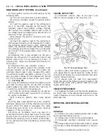
CHECKING FOR DIAGNOSTIC CODES
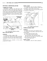
When trying to verify a speed control system elec-
tronic malfunction: Connect a DRB scan tool if avail-
able to the data link connector (Fig. 3). The connector
is located at left side of the steering column, and at
lower edge of the panel.
If a scan tool is not available, use the following
procedure:
(1) With key inserted in ignition switch, cycle
switch to ON position three times. On third cycle,
leave switch in ON position.
(2) After switch has been cycled three times,
observe MALFUNCTION INDICATOR LAMP (check
engine) indicator on instrument cluster. If a diagnos-
tic code is present, indicator will flash (blink) in a
series which will show which diagnostic code is the
problem. Example: A series of three flashes in rapid
succession, a slight pause, then four flashes in rapid
succession would indicate diagnostic code 34.
(3) A speed control malfunction may occur without
either diagnostic code being indicated. If no diagnos-
tic code appears or diagnostic code 15 or 34 is
observed, refer to the appropriate flow chart.
Refer to Group 25, for further information and use-
age of the DRB scan tool and a more complete list of
Diagnostic Trouble Code.
SPEED CONTROL ACCELERATES OR TAPS UP
BY ITSELF
Check for diagnostic trouble codes. If code 15 refer
to the Powertrain Diagnostic Manual, if code 34 per-
form the following test:
(1) Conduct the speed control switch test on the
RESUME/ACCEL switch.
(2) If it fails, replace switch.
(3) If it passes, disconnect the 4 way connector at
servo. Test continuity of pin 1 to ground to test for
intermittent short. Wiggle wires while preforming
test.
(4) If continuity to ground, repair wiring.
(5) If no continuity to ground, replace PCM.
SPEED CONTROL SLOWS DOWN BY ITSELF
Test vehicle speed sensor, refer to group 8E. If sen-
sor fails replace sensor, if it passes perform the fol-
lowing test:
(1) Perform the speed control switch test on the
SET/COAST switch, if it fails replace switch.
(2) If the switch passes, conduct the vacuum sup-
ply test.
Fig. 3 Data Link Connector Location
HOOD RELEASE
DIAGNOSTIC
CON-
NECTOR
DRIVER’S
SIDE
KICK PANEL
8H - 4
VEHICLE SPEED CONTROL SYSTEM
JA
DESCRIPTION AND OPERATION (Continued)
Summary of Contents for Stratus LHD 1997
Page 11: ......
Page 79: ......
Page 193: ......
Page 205: ......
Page 239: ......
Page 273: ......
Page 293: ......
Page 296: ...Charging System Schematic Typical JA CHARGING SYSTEM 8C 3 DIAGNOSIS AND TESTING Continued ...
Page 307: ......
Page 309: ......
Page 343: ...8D 34 IGNITION SYSTEM JA SPECIFICATIONS Continued ...
Page 377: ...8D 34 IGNITION SYSTEM JA SPECIFICATIONS Continued ...
Page 379: ......
Page 381: ......
Page 395: ......
Page 399: ......
Page 421: ......
Page 469: ......
Page 509: ......
Page 515: ......
Page 519: ......
Page 521: ......
Page 533: ......
Page 537: ......
Page 539: ......
Page 540: ......
Page 541: ......
Page 542: ......
Page 543: ......
Page 544: ......
Page 545: ......
Page 546: ......
Page 547: ......
Page 548: ......
Page 549: ......
Page 550: ......
Page 551: ......
Page 552: ......
Page 553: ......
Page 554: ......
Page 557: ......
Page 558: ......
Page 559: ......
Page 560: ......
Page 561: ......
Page 562: ......
Page 563: ......
Page 564: ......
Page 565: ......
Page 566: ......
Page 567: ......
Page 568: ......
Page 569: ......
Page 570: ......
Page 571: ......
Page 572: ......
Page 573: ......
Page 575: ......
Page 577: ......
Page 578: ......
Page 579: ......
Page 580: ......
Page 581: ......
Page 582: ......
Page 583: ......
Page 585: ......
Page 587: ......
Page 589: ......
Page 591: ......
Page 593: ......
Page 595: ......
Page 596: ......
Page 597: ......
Page 598: ......
Page 599: ......
Page 600: ......
Page 601: ......
Page 602: ......
Page 603: ......
Page 604: ......
Page 605: ......
Page 606: ......
Page 607: ......
Page 608: ......
Page 609: ......
Page 610: ......
Page 611: ......
Page 612: ......
Page 621: ......
Page 622: ......
Page 623: ......
Page 624: ......
Page 625: ......
Page 626: ......
Page 627: ......
Page 631: ......
Page 633: ......
Page 634: ......
Page 637: ......
Page 638: ......
Page 639: ......
Page 640: ......
Page 641: ......
Page 645: ......
Page 646: ......
Page 647: ......
Page 648: ......
Page 649: ......
Page 650: ......
Page 651: ......
Page 657: ......
Page 659: ......
Page 661: ......
Page 662: ......
Page 663: ......
Page 667: ......
Page 668: ......
Page 671: ......
Page 672: ......
Page 673: ......
Page 677: ......
Page 678: ......
Page 679: ......
Page 680: ......
Page 681: ......
Page 682: ......
Page 683: ......
Page 684: ......
Page 685: ......
Page 686: ......
Page 689: ......
Page 691: ......
Page 693: ......
Page 695: ......
Page 696: ......
Page 699: ......
Page 701: ......
Page 703: ......
Page 705: ......
Page 706: ......
Page 707: ......
Page 711: ......
Page 712: ......
Page 715: ......
Page 716: ......
Page 719: ......
Page 721: ......
Page 722: ......
Page 725: ......
Page 727: ......
Page 728: ......
Page 731: ......
Page 733: ......
Page 734: ......
Page 737: ......
Page 739: ......
Page 741: ......
Page 742: ......
Page 745: ......
Page 747: ......
Page 749: ......
Page 751: ......
Page 753: ......
Page 754: ......
Page 755: ......
Page 756: ......
Page 757: ......
Page 758: ......
Page 759: ......
Page 763: ......
Page 764: ......
Page 765: ......
Page 766: ......
Page 767: ......
Page 768: ......
Page 769: ......
Page 770: ......
Page 771: ......
Page 772: ......
Page 773: ......
Page 774: ......
Page 775: ......
Page 776: ......
Page 777: ......
Page 778: ......
Page 779: ......
Page 780: ......
Page 781: ......
Page 782: ......
Page 783: ......
Page 784: ......
Page 785: ......
Page 786: ......
Page 787: ......
Page 788: ......
Page 789: ......
Page 790: ......
Page 791: ......
Page 792: ......
Page 793: ......
Page 794: ......
Page 795: ......
Page 796: ......
Page 797: ......
Page 798: ......
Page 799: ......
Page 800: ......
Page 801: ......
Page 802: ......
Page 803: ......
Page 804: ......
Page 805: ......
Page 806: ......
Page 807: ......
Page 835: ...Fig 7 Body Splices 8W 95 6 8W 95 SPLICE LOCATIONS JA DESCRIPTION AND OPERATION Continued ...
Page 837: ......
Page 975: ...Adapter 6887 Camshaft Seal Installer 6863 9 138 2 5L ENGINE JA SPECIAL TOOLS Continued ...
Page 1001: ...13 6 BUMPERS AND FRAME JA SPECIFICATIONS Continued ...
Page 1065: ...Fuel Line Adapter 1 4 14 64 FUEL SYSTEM JA SPECIAL TOOLS Continued ...
Page 1071: ......
Page 1236: ...41TE TRANSAXLE HYDRAULIC SCHEMATIC JA TRANSAXLE 21 105 SCHEMATICS AND DIAGRAMS Continued ...
Page 1237: ...41TE TRANSAXLE HYDRAULIC SCHEMATIC 21 106 TRANSAXLE JA SCHEMATICS AND DIAGRAMS Continued ...
Page 1238: ...41TE TRANSAXLE HYDRAULIC SCHEMATIC JA TRANSAXLE 21 107 SCHEMATICS AND DIAGRAMS Continued ...
Page 1239: ...41TE TRANSAXLE HYDRAULIC SCHEMATIC 21 108 TRANSAXLE JA SCHEMATICS AND DIAGRAMS Continued ...
Page 1240: ...41TE TRANSAXLE HYDRAULIC SCHEMATIC JA TRANSAXLE 21 109 SCHEMATICS AND DIAGRAMS Continued ...
Page 1241: ...41TE TRANSAXLE HYDRAULIC SCHEMATIC 21 110 TRANSAXLE JA SCHEMATICS AND DIAGRAMS Continued ...
Page 1242: ...41TE TRANSAXLE HYDRAULIC SCHEMATIC JA TRANSAXLE 21 111 SCHEMATICS AND DIAGRAMS Continued ...
Page 1243: ...41TE TRANSAXLE HYDRAULIC SCHEMATIC 21 112 TRANSAXLE JA SCHEMATICS AND DIAGRAMS Continued ...
Page 1244: ...41TE TRANSAXLE HYDRAULIC SCHEMATIC JA TRANSAXLE 21 113 SCHEMATICS AND DIAGRAMS Continued ...
Page 1245: ...41TE TRANSAXLE HYDRAULIC SCHEMATIC 21 114 TRANSAXLE JA SCHEMATICS AND DIAGRAMS Continued ...
Page 1246: ...41TE TRANSAXLE HYDRAULIC SCHEMATIC JA TRANSAXLE 21 115 SCHEMATICS AND DIAGRAMS Continued ...
Page 1247: ...41TE TRANSAXLE HYDRAULIC SCHEMATIC 21 116 TRANSAXLE JA SCHEMATICS AND DIAGRAMS Continued ...
Page 1248: ...41TE TRANSAXLE HYDRAULICSCHEMATIC JA TRANSAXLE 21 117 SCHEMATICS AND DIAGRAMS Continued ...
Page 1271: ......
Page 1287: ...SPECIFICATIONS SUNROOF COMPONENTS 23 16 BODY JA ...
Page 1318: ...SPECIAL TOOLS BODY REMOVER MOLDINGS C 4829 STICK TRIM C4755 JA BODY 23 47 ...
Page 1319: ......
Page 1321: ...Fig 1 Floor Console 23 2 BODY JA REMOVAL AND INSTALLATION Continued ...
Page 1359: ......
Page 1387: ......
Page 1401: ...FASTENER IDENTIFICATION 6 INTRODUCTION JA GENERAL INFORMATION Continued ...
Page 1404: ...METRIC CONVERSION JA INTRODUCTION 9 GENERAL INFORMATION Continued ...
Page 1512: ...41TE TRANSAXLE HYDRAULIC SCHEMATIC JA TRANSAXLE 21 105 SCHEMATICS AND DIAGRAMS Continued ...
Page 1513: ...41TE TRANSAXLE HYDRAULIC SCHEMATIC 21 106 TRANSAXLE JA SCHEMATICS AND DIAGRAMS Continued ...
Page 1514: ...41TE TRANSAXLE HYDRAULIC SCHEMATIC JA TRANSAXLE 21 107 SCHEMATICS AND DIAGRAMS Continued ...
Page 1515: ...41TE TRANSAXLE HYDRAULIC SCHEMATIC 21 108 TRANSAXLE JA SCHEMATICS AND DIAGRAMS Continued ...
Page 1516: ...41TE TRANSAXLE HYDRAULIC SCHEMATIC JA TRANSAXLE 21 109 SCHEMATICS AND DIAGRAMS Continued ...
Page 1517: ...41TE TRANSAXLE HYDRAULIC SCHEMATIC 21 110 TRANSAXLE JA SCHEMATICS AND DIAGRAMS Continued ...
Page 1518: ...41TE TRANSAXLE HYDRAULIC SCHEMATIC JA TRANSAXLE 21 111 SCHEMATICS AND DIAGRAMS Continued ...
Page 1519: ...41TE TRANSAXLE HYDRAULIC SCHEMATIC 21 112 TRANSAXLE JA SCHEMATICS AND DIAGRAMS Continued ...
Page 1520: ...41TE TRANSAXLE HYDRAULIC SCHEMATIC JA TRANSAXLE 21 113 SCHEMATICS AND DIAGRAMS Continued ...
Page 1521: ...41TE TRANSAXLE HYDRAULIC SCHEMATIC 21 114 TRANSAXLE JA SCHEMATICS AND DIAGRAMS Continued ...
Page 1522: ...41TE TRANSAXLE HYDRAULIC SCHEMATIC JA TRANSAXLE 21 115 SCHEMATICS AND DIAGRAMS Continued ...
Page 1523: ...41TE TRANSAXLE HYDRAULIC SCHEMATIC 21 116 TRANSAXLE JA SCHEMATICS AND DIAGRAMS Continued ...
Page 1524: ...41TE TRANSAXLE HYDRAULICSCHEMATIC JA TRANSAXLE 21 117 SCHEMATICS AND DIAGRAMS Continued ...