


6 Setting up the 3D scanner system
3DPIXA
CD40131 Version 1
51 / 99
3. If the trigger devices are connected via the I/O ports of the frame grabber (see
chapter 5.5.3, p. 47), set the I/O port settings of the frame grabber correspondingly.
6.3
Setting up the Corona II Ilumination with XLC4
The Corona II Illumination is installed (see Corona II manual).
1. Turn on the power supply of the Corona II Illumination.
2. Wait until the red LED of the XLC4 controller illuminates for about 4 s, and the green LED
is blinking every 4 s.
The XLC4 controller is ready for operation.
3. Connect the XLC4 controller to the PC.
The XLC4 controller can be connected to the PC via the following interfaces (see
Corona II manual):
– RS232 (recommended)
– USB
– Ethernet
4. Configure the selected interface connection as described in the Corona II manual.
6.4
Setting up the CameraLink interface
The CameraLink interface can be set up with the Camera Setup Tool (CST) as described in
the allPIXA (pro) manual (see chapter 1.2, p. 7). The Medium mode is set by default.
For the 3DPIXA dual camera the CameraLink interface has to be set up for both cameras
separately. This can be done with two CST applications, which are opened at the same
time.
1. Open the CST.
2. Select the CameraLink port where the camera is connected (CameraLink port of the
frame grabber).
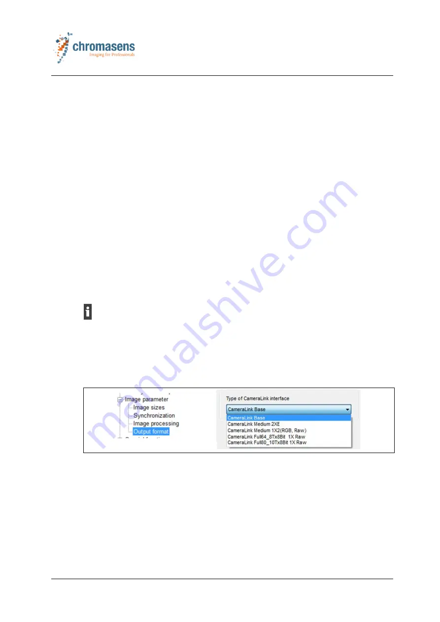
3. In the
Camera Settings
select
Output format
in the
Image parameter
folder.
Fig. 25: Setting up the CameraLink interface
4. In the
Type of CameraLink interface
dropdown list, select the desired CameraLink
interface.
For information on the CameraLink interface types refer to chapter 7.4.2, p. 84.
5. Select the
OK
button.
6. Save the settings to the non-volatile memory of the camera by selecting the
corresponding icon in the toolbar or by pressing the F10 key on the PC keyboard.


