chromasens 3DPIXA Manual Download Page 48

5  Installing the 3D scanner system 


48 / 99 

CD40131 Version 1 

3DPIXA 

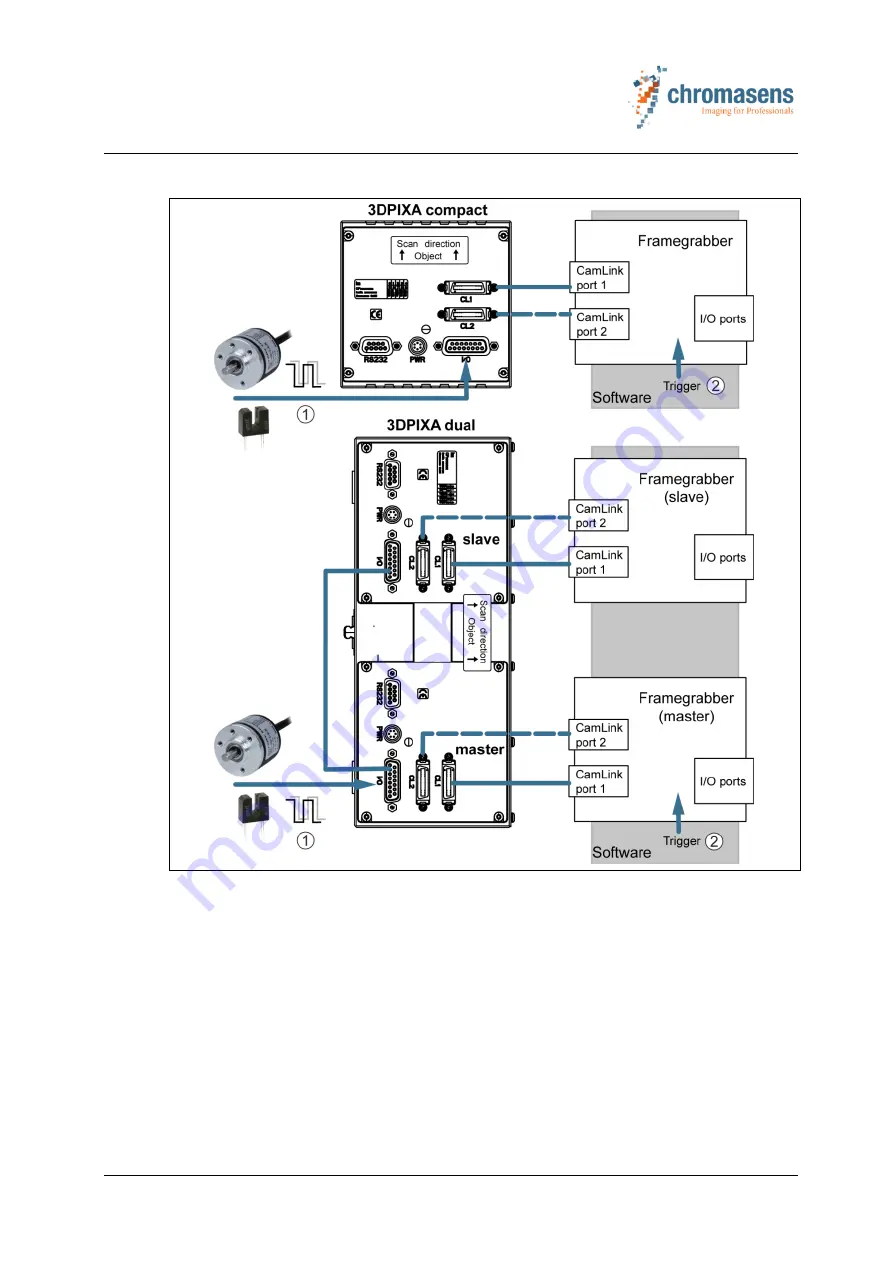
Connecting the trigger devices via the I/O port of the camera 


Fig. 24:  Trigger device connections via I/O port of the camera 

Trigger device connection (hardware trigger

)


Software trigger 


The hardware trigger signals are transferred via the I/O connection to the camera. 


Summary of Contents for 3DPIXA

Page 1: ...3D Line Scan Camera 3DPIXA Manual 3DPIXA Manual_R1 0 CD40131 Version 1...

Page 2: ...blems with the 3DPIXA camera that you cannot solve by yourself contact your local distributor or send us an email Chromasens GmbH Max Stromeyer Str 116 D 78467 Konstanz Germany Phone 49 0 7531 876 500...

Page 3: ...5 2 6 1 CameraLink frame grabbers 15 2 6 2 GPUs 16 2 7 Ambient conditions 16 2 8 Scope of supply 17 2 9 Optional accessories 17 3 Safety 18 3 1 Basic safety regulations 18 3 2 Safety instructions for...

Page 4: ...44 5 5 1 Overview of the 3DPIXA connections markers and status LED 44 5 5 2 Connecting the camera 45 5 5 3 Connecting the trigger device 47 6 Setting up the 3D scanner system 50 6 1 Commissioning the...

Page 5: ...3 Image sizes 83 7 3 1 Image start delay 83 7 4 Output format 84 7 4 1 Video output mode 84 7 4 2 CameraLink interface type and minimum line time integration time 84 7 4 3 Insert mode 85 7 5 Test patt...

Page 6: ...EC declaration of conformity 94 10 2 Connectors cables and pin assignment 95 10 2 1 Master Slave synchronization cable 95 10 2 2 Power supply PWR 96 10 2 3 Config UART serial RS232 96 10 2 4 Video Cam...

Page 7: ...d documents For certain operations the following manuals are useful for additional information Document Description Drawings and 3D CAD models Technical drawings see orange USB stick and CAD models CS...

Page 8: ...1 4 Firmware and software version in this manual This document refers to the following version CS 3D Software v2 3e Camera FW 1 69 CP000470 models 3 02 CP000520 models CST version 2 7 2 Build 11 Newe...

Page 9: ...s WARNING Hazardous situation or task which if not avoided may result in serious injury or death Measure for avoidance CAUTION Hazardous situation or task which if not avoided may result in minor or m...

Page 10: ...missioning of the 3DPIXA is not permitted until it has been verified that the machine or system in which the 3DPIXA is installed complies with the safety regulations and standards of the country in wh...

Page 11: ...solution m 3 10 Height range mm see Fig 2 p 13 2 6 8 2 Free working distance mm see Fig 2 p 13 99 6 0 1 173 6 0 1 Maximum speed for image acquisition mm s 310 630 CameraLink configurations Base Medium...

Page 12: ...fied values 3DPIXA dual CP000520 models CP000520 D02 005 0035 CP000520 D01 015 0105 CP000520 D02 200 1400 Optical resolution m px 5 15 200 Field of view mm see Fig 2 p 13 35 105 1400 Number of pixels...

Page 13: ...Fig 2 Dimensions FOV Field of view FWD Free working distance L Length H Height HR Height range W Width WD Working distance The reference positions of the used 3DPIXA model you will find in the corres...

Page 14: ...er mode Free run external trigger Operating temperature 0 C to 60 C 32 F to 140 F housing temperature Additional accessories Chromasens Corona II illumination Certifications CE FCC compliant RoHS Tab...

Page 15: ...frequency of 12 4 kHz Configuration 1 tap with 24 bits 1X 1 pixel with 24 bits Bandwidth 3 bytes 85 MHz pixel clock frequency 255 MBytes s CameraLink Medium configuration High performance of the 3DPI...

Page 16: ...sens de user Downloads System Requirements 3DPIXA System Requirements 2 7 Ambient conditions General ambient conditions Life phase Standard Operation IEC 721 3 3 IE33 Transport IEC 721 3 1 IE11 Storag...

Page 17: ...Viewer and CS 3D API software package CS 3D Viewer manual CS 3D API manual Technical drawings 3D camera models Camera CST parameter programming software CS API CS API manual allPIXA manual allPIXA pro...

Page 18: ...lines and intervals for regular inspection work Before starting maintenance work disconnect the 3DPIXA from the power supply Before starting maintenance work let heat sources such as heaters radiators...

Page 19: ...persons who have undergone electrotechnical training under the supervision of a qualified electrician in compliance with applicable electrotechnical regulations Only suitably trained and qualified pe...

Page 20: ...ed temperature voltage sensors which can be read out with the XLC4 controller By using the XLC4 controller the illumination unit can be monitored and kept stable 4 Frame grabber PC plug in card The im...

Page 21: ...age 8 Slave sensor 9 Master sensor 10 Slave image 11 Master image In both camera types 2 lenses 2 3 at a defined distance create images of the object 1 on a CCD sensor The CCD sensor of the 3DPIXA com...

Page 22: ...r portal at http www chromasens de user Downloads Whitepapers or contact our support 4 3 Principle functionality of a line scan sensor The 3DPIXA camera is equipped with trilinear CCD line scan sensor...

Page 23: ...ras the frame scan mode with FVAL is obligatory This mode ensures the correct synchronization between the two separate cameras of the 3DPIXA dual camera and frame grabber 4 3 2 Concept of image synchr...

Page 24: ...synchronized recording of each image line between the master camera and the slave camera 3 Due to the synchronized FVALs of the master camera and the slave camera also the image ends of the master cam...

Page 25: ...6 bit grey values The height in mm is determined from the height map image using the CS 3DAPI with calibration and configuration file 4 4 1 Pattern matching For pattern matching a correlation based ap...

Page 26: ...set and shading correction are both needed for the master and the slave camera The 3DPIXA camera offers the possibility to generate black offset and shading correction internally or offline For black...

Page 27: ...ite point stable in optimal conditions Fig 9 Closed loop control for white balancing With the 3DPIXA camera the area of an image can be defined as a reference and the reference values target values ca...

Page 28: ...ng table shows different illumination types and examples of use For information on the illustrated illumination devices refer to the Corona II manual More details can be found on our partner portal at...

Page 29: ...racy For accurate height measurement the images taken with the 3DPIXA camera must show as much texture of the scanned object as possible Textures in the images are an important pre condition for the p...

Page 30: ...ht measurement If we move our object closer to or further away from the 3DPIXA image sharpness and accuracy decrease with the distance to the focus point For the best height measurement results it is...

Page 31: ...r 6 13 p 76 To perform those steps the 3DPIXA has to be set into free running mode without external frame trigger and without external line trigger camera is in frame free run mode and line free run m...

Page 32: ...the master camera and slave camera The image heights have to be set identically for master camera and slave camera slave ignored Encoder line trigger master disabled No external encoder line trigger...

Page 33: ...synchronization of object movement with camera image capturing The external trigger signals are processed by the master camera The behavior of the slave camera is determined by the master camera Camer...

Page 34: ...n of the object and or the scanning position Line trigger The line trigger signal is typically generated by an encoder Encoders provide consecutive pulses which indicate the relative position change o...

Page 35: ...numbers of encoder pulses are possible If the line encoder reduction is used the transport resolution is reduced by the encoder reduction factor see chapter 0 p 86 Tab 12 Encoder modes 4 10 Setting co...

Page 36: ...ware to check live values from the camera and access to all parameters CS 3D API The CS 3D API is an SDK that provides you with functions to calculate 3D information in a fast and scalable manner This...

Page 37: ...fting table is especially recommended e g for a 3D demonstration scanner system and in cases in which it is difficult to lift up and down the 3DPIXA camera CameraLink Frame grabber s Depending on the...

Page 38: ...he frame start signal can be transmitted either directly via the I O port of the Master camera or via the frame grabber using a CameraLink cable see chapter 5 5 3 p 47 Encoder Line trigger Light barri...

Page 39: ...onents to reach their thermal equilibrium The 3D scanner system components must fulfill the following preconditions for accurate measurements Camera holder Use a camera holder that protects the camera...

Page 40: ...e glass plate of the camera Precise image capturing and 3D calculations are possible only if the camera is installed very precisely Tilting of the camera leads to image artifacts and or wrong calculat...

Page 41: ...n Fig 16 p 41 In the standard case the longitudinal and transverse axes of the camera are adjusted perpendicular 90 to the inspection plane see Fig 17 p 41 If the longitudinal alignment cannot be sati...

Page 42: ...to the transport plane and to the transverse direction 2 Incorrect camera alignment Depending on whether the target or the camera is moved for scanning the forward scan direction is as shown in Fig 1...

Page 43: ...ow install a fan and direct it at a large camera surface area 5 4 Preparing the 3D scanner system components For the installation of the Corona II Illumination refer to the Corona II manual 1 Install...

Page 44: ...s between the allPIXA pro camera and the PC 5 Power connection Hirose HR10A 7R 6P male for power supply 6 Digital port IO interface D Sub 15 female for the incremental encoder signal light barriers an...

Page 45: ...CameraLink Port 2 additionally required for medium mode 3 Master Slave synchronization Connect CL1 of the 3DPIXA camera to the first port of the frame grabber 1 If the camera will be operated in mediu...

Page 46: ...r these models a cable is included in the delivery see chapter 2 8 p 17 For the CP000520 models the synchronization is carried out internally 2 Connect the camera to the power supply Fig 22 Power supp...

Page 47: ...the 3DPIXA camera Alternatively or additionally the image acquisition can be triggered by the PC software Connecting the trigger devices via the I O ports of the frame grabber Fig 23 Trigger device c...

Page 48: ...onnecting the trigger devices via the I O port of the camera Fig 24 Trigger device connections via I O port of the camera 1 Trigger device connection hardware trigger 2 Software trigger The hardware t...

Page 49: ...tal encoder high optional 2 Light barrier high optional 3 nSelMaster bridge to 0 V closed by the supplied Master Slave cable see chapter 10 2 1 p 95 4 5 Open 6 Master Slave interface 7 0 V 8 Master Sl...

Page 50: ...e frame grabber manufacturer For detailed information on the setting options refer to the corresponding acquisition software documentation 1 Open the image acquisition software For correct image acqui...

Page 51: ...in the Corona II manual 6 4 Setting up the CameraLink interface The CameraLink interface can be set up with the Camera Setup Tool CST as described in the allPIXA pro manual see chapter 1 2 p 7 The Me...

Page 52: ...view of the settings which only have to be defined for the master camera Simple setup view Image parameters Frame start triggered frame scan Timing Integration time Line period Encoder setup Enable en...

Page 53: ...The simple setup tool is used to quickly configure the camera for the first image acquisitions 1 Select the green smiley button in the toolbar of the CST The simple setup tool is shown Fig 26 Simple...

Page 54: ...ree running mode i e with the encoder disabled When using a 3DPIXA dual camera the integration time line period is only set by the master camera see chapter 6 5 1 p 52 The following steps are intended...

Page 55: ...tion Select the Create references button This starts the wizard for black offset referencing and shading flat field referencing see chapter 0 p 76 and chapter 6 14 p 77 7 Set the video output paramete...

Page 56: ...n the currently active settings will be overwritten by the factory settings Displaying camera information When selecting the Display camera information button the following window is displayed Fig 27...

Page 57: ...mal user default has to be changed to expert user via the CST system configuration For the 3DPIXA dual camera the trigger inputs 1 4 have to be set only for the master camera Fig 28 User configurable...

Page 58: ...assignment Frame trigger Frame grabber CL1 CC3 CL1 CC4 depending on the frame grabber settings Camera I O port X5 1 9 X5 2 10 depending on the I O pin assignment Tab 16 Trigger device setup When the E...

Page 59: ...f encoder pulses per line exceeds 255 this factor has to be used to reduce the number below 255 Average size Number of encoder increments which are averaged for speed measurements Encoder resolution E...

Page 60: ...time s Desired transport resolution mm pixel Nominal transport speed mm s If the transport resolution is stated in dpi and the speed in metric values the values have to be converted 1 inch 25 4 mm Exa...

Page 61: ...Tab 18 Examples for images Count the pixels in the center of the image for an accurate determination 4 If distortion exists calculate the new moving speed and or the integration time as follows Count...

Page 62: ...efore not necessary to make settings in Master Slave mode for the first startup or standard operation For 3DPIXA dual starting with the article code CP00470 an external Master Slave synchronization ca...

Page 63: ...ve mode via the CST 1 Open the CST for the master camera and for the slave camera and disable Display only compatible cameras If no selection window is shown after opening the CST select the Set syste...

Page 64: ...uses the FVAL when capturing images 1 In the Camera Settings select Output format in the Image parameter folder Fig 32 Enabling First Line Info block 2 Activate First Line Info block in the CST for t...

Page 65: ...rection the calibration has to be switched to the inverted transport direction in the CS 3D API This is done by the parameter invertTransportDirection in the configuration file To set the scan directi...

Page 66: ...CS API refer to the CS API manual 6 10 Adjusting the integration and line period times 1 Open the CST 2 Select the COM port where the camera is connected COM port of the frame grabber 3 In the Camera...

Page 67: ...used the settings must be identical for both cameras For this open the CST application for each camera For the 3DPIXA dual camera the timing and trigger parameters have to be set only for the master...

Page 68: ...he brightness of the images Check your frame grabber software whether a line profile is available Fig 38 Identifying the brightest areas in the images 1 Maximum brightness 4 In the Camera Settings sel...

Page 69: ...ter saving the new value in the volatile memory of the camera by selecting the appropriate toolbar icon or by pressing the F9 key Fig 40 Adjusting the white reference marks 1 Moving the white referenc...

Page 70: ...value Parameter modifications 200 1 Increase the intensity of the illumination 2 Increase the integration time 3 Increase the analog coarse gain 80 1 Decrease the analog coarse gain 2 Decrease the in...

Page 71: ...Parameter Gain and reference settings Enable continuous white control Disabled Update start gain with current gain values Enabled Tab 21 Adjusting the start gain values Now the values in the Start ga...

Page 72: ...e the brightness of the images Check your frame grabber software whether a line profile is available Fig 43 Identifying the brightest area in the image 1 Maximum brightness 4 In the Camera Settings se...

Page 73: ...e volatile memory of the camera by selecting the appropriate toolbar icon or by pressing the F9 key Fig 45 Adjusting the white reference mark 1 Moving the white reference mark rightwards by increasing...

Page 74: ...lue Parameter modifications 200 Increase the intensity of the illumination Increase the integration time Increase the analog coarse gain 80 Decrease the intensity of the illumination Decrease the inte...

Page 75: ...side of the image The current white reference levels should be between 780 and 820 18 Set the checkmark in the Enable continuous white control box 19 Perform tap balancing by selecting the appropriat...

Page 76: ...e 5 Select image source 2 Create reference internally 6 Select the Next button 7 Remove the checkmark from the Perform white balancing box For the 3DPIXA camera it is not recommended to perform white...

Page 77: ...chapter 6 13 p 76 For the 3DPIXA dual camera the shading white flat field referencing has to be performed for the master camera and the slave camera 1 Make sure that the white reference is at the bes...

Page 78: ...ated Use at least 500 lines for calculating the reference values in order to eliminate noise The values used for the reference will be calculated by averaging each column in the selected area 12 Selec...

Page 79: ...he camera 3 Acquire a well illuminated raw image with texture With the 3DPIXA dual camera 2 raw images are required The image s should have the following properties 24 bit bitmap format 7296 pixels im...

Page 80: ...t different output pixel clocks refer to chapter 7 4 2 p 84 7 2 Gain and reference 7 2 1 Target white reference values Function Video value for the desired value of the closed loop control for white b...

Page 81: ...e image center will be saturated Fig 51 Raw video values red theoretical maximum values green and dark reference values blue as a function of the number n of pixels with 10 bit GUI value range 1 Contr...

Page 82: ...the camera with current gaining values in a range from 80 200 for best image quality by using the Analog Coarse Gain function to pre adjust the actual gain range If the output signal of the CCD is hig...

Page 83: ...igger can be taken internally or externally Channels All Type Integer Dependency Only in frame scan mode Notes Camera Value CST Lower limit All 0 Upper limit All 32767 Fig 52 Vertical synchronization...

Page 84: ...x see the tables below For Base mode the CameraLink connector 1 has to be used For an overview of the CameraLink interface types see chapter 2 6 1 p 15 Minimum line time integration time for different...

Page 85: ...required Info block in each line Line related information is shown in the first 10 or 17 pixels of each line depending on the selections for Insert Mode For detailed information on the each line and...

Page 86: ...n 5 Change video level at every pixel 7 6 Line trigger and encoder setup line synchronization In case the camera is used in the Triggered Frame Scan with active line trigger or encoder the linesync en...

Page 87: ...e Fig 54 Line trigger and camera pulses 1 Line trigger 2 Integration time Encoder mode The camera measures the distance of the signals and will send lines with the requested resolution An internal lin...

Page 88: ...ected Encoder mode at the Synchronization mode Notes For the use of this mode the external ports have to be connected to the internal function by using the IO Configurator of CST One Channel full step...

Page 89: ...ronization mode Notes Refers to a full increment of the encoder The value Encoder pulses per line is internally calculated by the camera and may not exceed 255 Recommended values are between 0 5 and 2...

Page 90: ...and Integration time have to be suitable to the transport speed The time for one line speed divided by resolution should be longer than the shortest possible integration time In case of higher speed t...

Page 91: ...or cleaning the camera Cleaning process 1 Wipe all surfaces requiring cleaning with a soft lint free cloth which may be moistened with Isopropanol 2 Inspect the camera and make sure that the cleaning...

Page 92: ...e actual status of the camera After booting is finished the camera continuously performs self checks If an error is detected the camera will indicate this by changing the LED color LED color Meaning O...

Page 93: ...e following image Fig 59 Image from the camera in safety mode Step 3 Final safety shutdown When the temperature is still exceeding the critical internal temperature the camera hardware is shut down to...

Page 94: ...10 Appendix 94 99 CD40131 Version 1 3DPIXA 10 Appendix 10 1 EC declaration of conformity...

Page 95: ...ntal encoder high optional Open 2 Light barrier high optional Open 3 nSelMaster bridge to 0 V Open internal pull up 4 5 Open Open 6 Master Slave interface Master Slave interface 7 0 V 0 V 8 Master Sla...

Page 96: ...ed for internal function do not connect 5 GND Ground 6 Not connected 7 CST Hardware Reset Input should be left open if unused 8 Not connected 9 Not connected Tab 26 Pin assignment of the RS232 connect...

Page 97: ...V over 100 Ohm Power Output 6 LVCMOS GPIO_P3 Master Slave interface 7 0 V Ground 8 LVCMOS GPIO_N4 Master Slave interface 9 RS422 GPIO_N0 Incremental encoder low 10 RS422 GPIO_N1 Light barrier low 11...

Page 98: ...green and blue Inside the camera the spatial differences of the pixel lines are corrected Shading flat field correction Corrects the brightness inhomogeneity resulting from lens illumination and non u...

Page 99: ...99 99 CD40131 Version 1 3DPIXA_Manual_R1_0 June 2018 Copyright by Chromasens GmbH Chromasens GmbH Max Stromeyer Stra e 116 78467 Konstanz Germany Phone 49 7531 876 0 Fax 49 7531 876 303 www chromasen...

Reviews: