4-38
J Series 2.0, 2.4, and 3.0kW Service Manual
020-100739-01 Rev. 1 (01-2012)
Section 4: Parts and Module Replacement
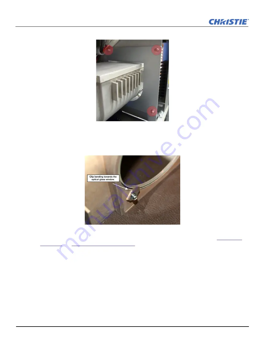
10. Remove the 3 screws securing the panel and then slide the light tube away from the lens.
11. Put on a pair of nitrile gloves and then remove the 3 screws and metal clips securing the optical window.
12. Clean the new optical window with compressed air and then place it in the recessed area on the light tube.
13. Attach the 3 clips to the light tube, aligning the holes in the clips with the holes in the light tube. Ensure
that the bent end of the clip is toward the optical window.
14. Tighten the 3 screws evenly a few threads at a time.
After replacing the light tube, if there are shadows on
the edges of a full white image, the integrator or fold mirror may need to be adjusted.
See
Fold Mirror
Adjustment
and
Integrator Assembly Adjustment
.
Summary of Contents for J 2.0kW
Page 1: ...J Series 2 0 2 4 and 3 0kW S e r v i c e M a n u a l 020 100739 01 ...
Page 2: ......
Page 3: ...J Series 2 0 2 4 and 3 0kW S e r v i c e M a n u a l 020 100739 01 ...
Page 12: ......
Page 16: ......
Page 70: ......
Page 72: ......
Page 74: ......
Page 88: ......
Page 92: ......
Page 93: ......


