Charger CWQC50 Installation Manual Download Page 3

3

SECTION I • INTRODUCTION 

Your new Reverse Osmosis (RO) Drinking Water System uses a combination of filtration technologies to reduce unwanted 

contaminants in a water supply. The following steps combine to give you the best in clear sparkling drinking water. 

MECHANICAL FILTRATION/ACTIVATED CARBON 

The sediment/carbon modules are designed to reduce the larger particles such as silt, rust, and scale. Its 5 micron (equal 

to 0.0002 inch) nominal rating helps to give maximum life to the RO Membrane. The activated carbon in the modules, 

has been designed to reduce any chlorine that may be present in the feed water. This pretreatment is also necessary for 

membrane protection. 

REVERSE OSMOSIS MEMBRANE 

The RO Membrane is the heart of the filtration system. It is designed to reduce the dissolved mineral content of the water. 

Minerals picked up in the environment, by the water, are measured as Total Dissolved Solids (TDS). In the Reverse Osmosis 

process, dissolved minerals are separated from the incoming water (Feed Water) to produce the product water (Permeate). 

The excess minerals are rinsed to drain (Reject Water).

The membrane is a specially constructed, fully aromatic polyamide film and is classified as a Thin Film Composite (TFC). The 

spiral wound construction of the RO Membrane provides maximum surface area for water production and is less susceptible 

to fouling by particulate matter, turbidity, and colloidal materials.

IN–LINE ACTIVATED CARBON POST FILTER 

The In–Line Activated Carbon Post Filter is located after the Holding Tank and has been designed to reduce the tastes and 

odors that may pass through the system. It adds a final polish to the water.

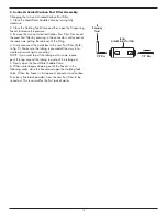
AUTOMATIC SHUTOFF VALVE 

The ASO Valve senses when the Holding Tank is full and closes the feed water supply to prevent excess reject water from 

going to drain when the unit is not producing water.

Summary of Contents for CWQC50

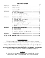
Page 1: ...INSTALLATION OPERATION AND SERVICE MANUAL RO DRINKING WATER SYSTEM MODEL CWQC50...

Page 2: ...D VIEW AND PARTS LIST 18 CAUTION All individuals should take adequate precautions when changing the filter cartridges including protective gloves to avoid direct contact with the exhausted cartridges...

Page 3: ...ls picked up in the environment by the water are measured as Total Dissolved Solids TDS In the Reverse Osmosis process dissolved minerals are separated from the incoming water Feed Water to produce th...

Page 4: ...mbrane that has been rinsed for 24 hours The production rate of a new Membrane can decrease by 10 per year or more depending upon the scaling and fouling tendencies of the Feed Water TABLE B RECOMMEND...

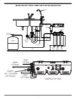
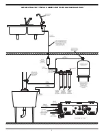
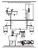
Page 5: ...5 MODEL CWQC50 TYPICAL UNDER SINK INSTALLATION DIAGRAM...

Page 6: ...6 MODEL CWQC50 TYPICAL UNDER SINK INSTALLATION DIAGRAM...

Page 7: ...7 MODEL CWQC50 TYPICAL UNDER SINK INSTALLATION DIAGRAM...

Page 8: ...Extra plastic tubing Low range air pressure gauge Bicycle hand air pump or compressor Small bottle of liquid chlorine bleach Graduated measuring cylinder Paper towels whisk broom and assorted clean u...

Page 9: ...a licensed plumber check with the local plumbing authority prior to installation In restricted under sink areas it may be easier to install the faucet first Allow adequate tubing lengths for any final...

Page 10: ...not supplied into the Faucet Base opening This will separate and orient the Toggle Wings Position the Faucet Base so that the arrows are pointing in the direction that the faucet handle will face Tigh...

Page 11: ...groove to prevent distortion of the tubing for larger tubing up to 5 8 OD use the large groove of the back plate Assemble and tighten the brass screw To pierce the tubing turn the Valve Handle fully c...

Page 12: ...n of a mounting plate 1 The mounting bracket will accept either 10 or 12 5mm mounting screws spaced on 7 1 8 18 1 cm centers Allow at least 2 5 08 cm of clearance beneath the filter housings to accomm...

Page 13: ...reconnect to the manifold plate 2 Start rinsing the system Slowly open the Feed Water Saddle Valve counterclockwise to its fully open position Open the faucet to allow air to escape while system is fi...

Page 14: ...ensing Faucet This will allow the manifold to be de pressurized so you can safely remove the old modules 2 Loosen and remove the Sediment Carbon Pre and Carbon Post Filter Modules 2 Press upward and t...

Page 15: ...lytubes to the new Post Filter Refer to Fig 5 Make sure the tubing is pressed all the way in to create a pressure tight connection NOTE If you want to pull the tubing out for some reason push the ring...

Page 16: ...water from Holding Tank and with the faucet open adjust the air pressure to 5 7 psig 35 48 kPa range Holding Tank Valve is partially closed Open Valve The Dispensing Faucet is out of adjustment or fau...

Page 17: ...ter overflows at the Dispensing Faucet Air Gap is blocked Clear Air Gap Rinse with vinegar for removal of calcium buildup Drain tubing is clogged Clear tubing Drain Clamp hole is misaligned Align with...

Page 18: ...18 EXPLODED VIEW 1 2 3 5 6 7 8 9 10 11 14 14 15 12 13 4 OUT IN S7206W JG In line Activated Carbon Post Filter 16...

Page 19: ...ner 1 12 S2116 6 Drain Restrictor 60 gpd 227 lpd 1 13 PK A6TEU4 MG Elbow Stem x 3 8 QC 1 14 S3551A 01 Sediment Carbon CS Module 2 15 S35715A 01 Membrane 50GPD Module 1 16 S7206W JG In line Activated C...

Page 20: ...d freezing or hot water All replacement filters and membranes must be Charger Water Treatment Products filters and membranes or the warranty is void If the unit is altered by anyone other than Charger...

Reviews: