


10
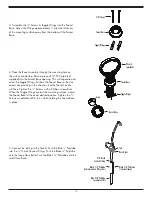
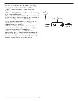
3. Assemble the
1
⁄
8
” Screws & Toggle Wings into the Faucet
Base. Adjust the Wings approximately 1” plus the thickness
of the mounting surface away from the bottom of the Faucet
Base.
5. Connect the tubing to the Faucet. Push the Blue
3
⁄
8
” Polytube
into the
3
⁄
8
” Quick Connect Fitting. Push the Black
3
⁄
8
” Polytube
onto the large Hose Barb. Push the Black ¼” Polytube onto the
small Hose Barb.
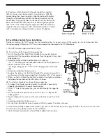
4. Place the Base Assembly through the mounting hole on
the sink or countertop. Place a piece of 3/4" PVC pipe (not
supplied) into the Faucet Base opening. This will separate and
orient the Toggle Wings. Position the Faucet Base so that the
arrows are pointing in the direction that the faucet handle
will face. Tighten the
1
⁄
8
” Screws with a Phillips screwdriver.
When the Toggle Wings contact the mounting surface, adjust
the Faucet Base to the exact desired position. Tighten the
1
⁄
8
”
Screws an additional 2-3 turns while holding the Faucet Base
in place.
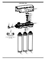
1/8" Screws
Faucet Base
Toggle Wings
3/8" Quick
Connect Fitting
Black 1/4" Polytube
(to drain port on RO system)
Blue 3/8" Polytube
(product outlet)
Black 3/8" Polytube
(to drain clamp)
Hose Barbs
Tab
Toggle Wings
Faucet Base
Wrench
(provided)
Faucet Base
Arrow
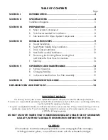
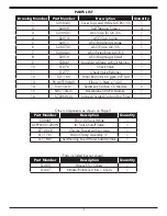
Summary of Contents for CWQC50
Page 1: ...INSTALLATION OPERATION AND SERVICE MANUAL RO DRINKING WATER SYSTEM MODEL CWQC50...
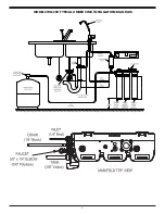
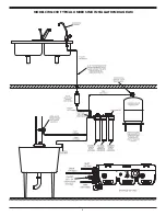
Page 5: ...5 MODEL CWQC50 TYPICAL UNDER SINK INSTALLATION DIAGRAM...
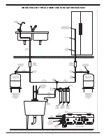
Page 6: ...6 MODEL CWQC50 TYPICAL UNDER SINK INSTALLATION DIAGRAM...
Page 7: ...7 MODEL CWQC50 TYPICAL UNDER SINK INSTALLATION DIAGRAM...


