2
Remote Control
2.1 Remote control basis
17
of the instrument. The associated parallel query enable register (PPE) determines which data bits of the
STB act on the IST mark.
4) Output buffer
The output buffer stores the message returned by the instrument to the controller. It does not belong to
the status report system, but determines the value of M bit of the STB.
For details of above register descriptions, please refer to “2.1.6 Status reporting system”.
SRE, ESE
The SRE can be used as an enable part of the STB. Similarly, the ESE can be used as an enable part of
the ESR.
2.1.5.2 Structure of SCPI Status Register
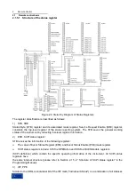
Each standard SCPI register consists of 5 parts. Each part contains 16 data bits and is functionally
independent. For example, each hardware status will be assigned with a data bit, and it is valid for all 5
parts of the register. If the Bit15 is set to 0, it means that the value of the register is a positive integer.
Figure 2.4 Status Register Structure
The above Figure shows that the status register is composed of 5 parts, which are described as follows:
Condition register
This part will be directly written by hardware or low-level register digit, which will reflect the current
working state of the instrument. This register is read-only and cannot be written. Reading will not clear
any value.
Positive and negative conversion register
Two transfer registers define the status transfer bit of the condition register stored in the event register.
The positive conversion register is similar to the conversion filter. When a certain data bit of the condition
NOTE

