background image

This manual is suitable for the following models of noise figure analyzer: 

3986A Noise figure analyzer (10 MHz


- 4GHz)

3986D Noise figure analyzer (10 MHz - 18GHz)

3986E Noise figure analyzer (10 MHz - 26.5GHz)

3986F Noise figure analyzer (10 MHz - 40GHz)

3986H Noise figure analyzer (10 MHz - 50GHz)

Options: 

3986-H01,  16603/16604  series  noise  source:  used  as  a  noise  power  standard  for  noise  figure
measurements.

3986-H02,  711XX  series high-performance  co-axial  adapter:  used  to  connect  the  noise  source  to
the noise figure analyzer.

3986-H03,  multi-core  cable:  used  for  smart  noise  source  driver  interface  and  noise  source

connection of noise figure analyzer.

3986-H04,  BNC(m)-BNC(m):  used  for  connection  of  standard  noise  source  driver  interface  and
standard noise source for noise figure analyzer

3986-H05,  aluminum  alloy  transportation  case:  high-strength,  lightweight  aluminum  alloy
transportation case that comes with handle and wheels for ease of transport.

3986-H98, English option: English display, English manual, English interface, and English operating
system.

Summary of Contents for 3986 Series

Page 1: ...3986 Series Noise Figure Analyzer Programming Manual...

Page 2: ...h performance co axial adapter used to connect the noise source to the noise figure analyzer 3986 H03 multi core cable used for smart noise source driver interface and noise source connection of noise...

Page 3: ...ation measurements have been carried out based on national standards Related information is available to the user for reference Quality Environmental Management The quality and environmental managemen...

Page 4: ......

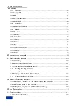
Page 5: ...ce and synchronization 13 2 1 5 Status reporting system 15 2 1 6 Error Queue 20 2 1 7 Programming considerations 21 2 2 Remote interface and its configuration 22 2 2 1 LAN 22 2 2 2 GPIB 23 2 3 I O lib...

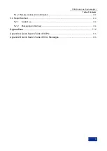
Page 6: ...e 100 4 1 Basic operation example 100 4 1 1 VISA library 100 4 1 2 Example running environment 101 4 1 3 Initialization and default status setting 102 4 1 4 Sending of setting command 103 4 1 5 Readin...

Page 7: ...f Contents 3 5 1 2 Remote control error information 112 5 2 Repair Method 114 5 2 1 Contact us 114 5 2 2 Packaging and delivery 114 Appendixes 116 Appendix A Quick Search Table of SCPIs 116 Appendix B...

Page 8: ...3986 Series noise figure analyzer Table of Contents 4...

Page 9: ...Remote Control This chapter introduces the remote control methods of the instrument so that the user can rapidly master the method to control the instrument in a remote way It is further divided into...

Page 10: ...of the instrument and aid users in learning the most common measurement procedures Main chapters included in this manual are as follows Overview Start Guide Operation Guide Button categories and menu...

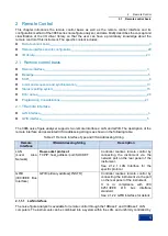
Page 11: ...interfaces LAN and GPIB The description of the remote interface and associated VISA addressing string is as shown in the following table Table 2 1 Remote Interface Type and VISA Addressing String Rem...

Page 12: ...be guaranteed to be smooth Set the address to the subnet where the main control computer resides by using the Local IP command of the noise figure analyzer For example if the IP address of the main c...

Page 13: ...n details in the ANSI IEEE standard 488 1 1987 and the ANSI IEEE standard 488 2 1992 For details of the standard please refer to the IEEE website http www ieee org The GPIB processes information in by...

Page 14: ...n The SCPI consists of a command header and one or more parameters which are separated by a space The command header contains one or more key fields The command with question mark as postfix is a quer...

Page 15: ...ation Remote control message The remote control message is a combination of one or more correctly formatted SCPIs It guides the equipment to measure and output the signal Response message The response...

Page 16: ...arameters An example of a syntax declaration SOURce POWer LEVel 10dBm In the above example the LEVel portion of the command immediately follows POWer with no separating space The following part LEVel...

Page 17: ...path SOURce LIST DWELl val val A semicolon separates 2 adjacent commands without affecting the current path FREQ 2 5GHZ POW 10DBM White space characters such as space or tab are generally ignored so l...

Page 18: ...equency offset function on FREQuency OFFSet STATe ON FREQuency OFFSet STATe 1 FREQ OFFS STAT ON FREQ OFFS STAT 1 Each parameter type corresponding to one or more response data types During query a num...

Page 19: ...as an exponent E009 200 MHz The MHz can be used as an exponent E006 100 mV 100 millivolts 10DEG 10 Degree MAXimum Maximum valid setting MINimum Minimum valid setting UP Increase a step DOWN Decrease a...

Page 20: ...ptional sign bit 100 Leading allowed 100 Leading allowed 256 No decimal point Discrete response data The discrete response data and discrete parameters are basically the same The main difference is th...

Page 21: ...EOI EOI and the last data byte Commands in command line are separated by semicolons and commands for different subsystems begin with a colon For example MMEM COPY Test1 MeasurementXY HCOP ITEM ALL Th...

Page 22: ...mming the computer can be forced to wait for some time to synchronize certain events The details are separately described below Controller program uses multiple threads Multi threads are used to wait...

Page 23: ...the overlapped command only and do not send OPC OPC or WAI 3 Send OPC ESR in the timer for cyclic query of completion status of operation If the return value LSB is equal to 1 this indicates that the...

Page 24: ...ng low level register information 2 ESR SCPI status register STB receives the information of the following registers The value of Event Status Register ESR and Event Status Enable ESE mask register SC...

Page 25: ...bits and is functionally independent For example each hardware status will be assigned with a data bit and it is valid for all 5 parts of the register If the Bit15 is set to 0 it means that the value...

Page 26: ...data sum bit Enable bit 0 The associated event bit does not act on the data sum Enable bit 1 The associated event bit acts on the data sum This part is read write and no value will be cleared after re...

Page 27: ...y querying the event status register 6 MSS bit master status summary bit This bit is set if the instrument triggers a service request 7 Operation status register data sum bit This bit can be set if th...

Page 28: ...tion in the error queue for specific error message 6 User request This bit is set if the instrument is switched to the manual control mode 7 Power on This bit is set when the instrument is powered on...

Page 29: ...g up the instrument remotely you need to initialize the instrument status for example send RST and then implement the desired status settings 2 Command sequence In general the setting and query comman...

Page 30: ...re The noise figure analyzer can also be controlled by connecting USB keyboard and mouse It is not possible to remotely control the instrument via this port 2 2 1 1 Connection The 3986 noise figure an...

Page 31: ...fy the subnet mask which is fixedly set to 255 255 255 0 in the instrument 2 2 2 GPIB Connection 23 Interface configuration 23 2 2 2 1 Connection 3986 noise figure analyzer is connected to an external...

Page 32: ...This is the main functional part of the instrument driver and can be understood as the framework program of the instrument driver 2 Interactive developer interface For user s convenience a graphical i...

Page 33: ...ry to provide two types of drivers in order to meet the demands of different users in different development environments The IVI driver of the noise figure analyzer uses Nimbus Driver Studio to produc...

Page 34: ...ands The common command is used to control general functions including the instrument status register status report synchronization and data storage The application method and function of the common c...

Page 35: ...e version number Example CETC41 3986 1312 8000K26 100005 1 30 Description Only query OPC Function description Set Query operation completion After all the commands to be processed are executed set bit...

Page 36: ...n Range 0 255 STB Function description Query status byte Return value Range 0 255 TRG Function description Execute the trigger command Description Only set WAI Function description Wait for execution...

Page 37: ...q Stop Freq Points Fixed Freq BW and List The user can set the frequency measurement range by using Start Freq and Stop Freq or set the frequency measurement range by using Cent Freq and Span Freq Mod...

Page 38: ...MHz 39 99995 GHz 3986H 10 05 MHz 49 99995 GHz Example SENS FREQ CENT 3GHz SENS FREQ CENT Key path Front panel Freq Points Cent Freq Start Frequency SENSe FREQuency STARt Function description This com...

Page 39: ...path Front panel Freq Points Stop Freq Points SENSe SWEep POINts Function description This command is used to set query the sweep points Setting format SENSe SWEep POINts number Query format SENSe SW...

Page 40: ...z kHz MHz GHz or k M G It is Hz by default freq Fixed frequency Range 3986A 10 MHz 3 99 GHz 3986D 10 MHz 17 99 GHz 3986E 10 MHz 26 49 GHz 3986F 10 MHz 39 99 GHz 3986H 10 MHz 49 99 GHz Example SENS FRE...

Page 41: ...ting format SENSe FREQuency SPAN FULL Example SENS FREQ SPAN FULL Key path Front panel Freq Points Page Up Full Sweep Width 3 3 2 Average BW The average corresponds to the Avg key on the front panel a...

Page 42: ...oint average SWE Sweep average Parameter description POINt during the sweep averaging is performed at each point based on the set number of average before the measurement is carried out at the next po...

Page 43: ...mode editing excess noise ratio table specifying a cold temperature specifying a fixed cold temperature selecting a fixed frequency excess noise ratio and setting SNS ENR Mode SENSe CORRection ENR MO...

Page 44: ...detected after it is powered on The SNS is connected when the command setting status is ON OFF 0 The status is off Example SENS CORR ENR AUTO STAT OFF SENS CORR ENR AUTO STAT Reset status Common tabl...

Page 45: ...ion TABLe ID DATA 346C SENSe CORRection ENR CALibration TABLe ID DATA Key path Front panel ENR Common Table Off Calibration ENR Table Model ID Calibration ENR Table Serial Number SENSe CORRection ENR...

Page 46: ...ault unit is Hz value ENR value in dB Range 1 81 data groups Example SENSe CORRection ENR MEASurement TABLe DATA 1GHz 15 31dB 2G 15 5 SENSe CORRection ENR MEASurement TABLe DATA Key path Front panel E...

Page 47: ...ble Off Measurement ENR Table Serial Load Measurement ENR Table from SNS Noise Source SENSe CORRection ENR MEASurement TABLe SNS Function description This command is used to load the ENR data from the...

Page 48: ...Se CORRection ENR THOT value Example SENSe CORRection SPOT MODE ENR SENSe CORRection SPOT MODE Reset status ENR Key path Front panel ENR ENR Mode Spot Spot Spot Mode ENR THot ENR THot SENSe CORRection...

Page 49: ...from the connected smart noise source and use cold temperature user cold temperature values Setting format SENSe CORRection TCOLd USER SET Example SENSe CORRection TCOLd USER SET Key path Front panel...

Page 50: ...rement A single fixed loss value that is applied to all frequencies can be specified or the loss compensation table applying to the frequencies within the entire frequency range corresponding to the l...

Page 51: ...e SENSe CORRection LOSS BEFore VALue 5dB SENSe CORRection LOSS BEFore VALue Key path Front panel Loss Comp Before DUT Fixed Fixed Value before DUT Reset status 0 dB Loss Compensation Table Data before...

Page 52: ...default unit returned by the query is K Range 0 29650000 00 K Example SENSe CORRection TEMPerature BEFore 1000K SENSe CORRection TEMPerature BEFore Key path Front panel Loss Comp Temp Before Reset sta...

Page 53: ...00 dB Example SENSe CORRection LOSS AFTer VALue 5dB SENSe CORRection LOSS AFTer VALue Key path Front panel Loss Comp After DUT Fixed Fixed After Reset status 0 dB Loss Table Data after DUT SENSe CORRe...

Page 54: ...290 0K 3 3 5 Mode Setup The mode set corresponds to the Mode Setup key on the front panel which is used for selecting the type of device under test setting mode measurement configuring external local...

Page 55: ...is fixed This command is only used when measuring up or downconverter devices or system down converter System DownConverter Control SENSe CONFigure MODE SYSTem DOWNconv STATe Function description Thi...

Page 56: ...The unit is Hz Parameter description The input frequency units include Hz kHz MHz GHz or k M G It is Hz by default frequency Fixed frequency Range 1Hz 300GHz Example SENSe CONFigure MODE SYSTem LOSCil...

Page 57: ...command is used to set query the measurement frequency input type of the system down converter Setting format SENSe CONFigure MODE SYSTem FREQuency CONText RF IF Query format SENSe CONFigure MODE SYST...

Page 58: ...LO frequency Range 1Hz 300GHz Example SENSe CONFigure MODE DOWNconv LOSCillator FREQuency 3GHz SENSe CONFigure MODE DOWNconv LOSCillator FREQuency Reset status 30GHz Key path Front panel Mode Setup DU...

Page 59: ...NFigure MODE UPConv IF FREQuency Function description This command is used to set query the upconverter fixed IF frequency Setting format SENSe CONFigure MODE UPConv IF FREQuency freq Query format SEN...

Page 60: ...signal frequency LO frequency USB Upper sideband signal frequency LO frequency DSB Double sideband no frequency offset Example SENSe CONFigure MODE UPConv LOSCillator OFFSet DSB SENSe CONFigure MODE...

Page 61: ...e Reset status OFF Key path Front panel Mode Setup DUT Setup Ext LO Config External Local Oscillator Input Power SENSe CONFigure MODE DUT EXTend LO POWer Function description This command is used to s...

Page 62: ...CONFigure LOSCillator PARameter MULTiplier 2 SENSe CONFigure LOSCillator PARameter MULTiplier Reset status 1 Key path Front panel Mode Setup Ext LO Config Multiplier External Local Oscillator Divider...

Page 63: ...SENSe SYSTem COMMunicate GPIB EXTLoscillator ADDRess Return value Integer Parameter description integer Integer range 1 30 Example SENSe SYSTem COMMunicate GPIB EXTLoscillator ADDRess 19 SENSe SYSTem...

Page 64: ...DUT Output Match CALCulate UNCertainty DUT MATCh OUTPut Function description This command is used to set query the output match of the device under test without any unit Setting format CALCulate UNCer...

Page 65: ...Calculator Instrument Gain Uncertainty Instrument Input Match CALCulate UNCertainty INSTrument MATCh INPut Function description This command is used to set query the instrument input match without any...

Page 66: ...alue Noise figure uncertainty Parameter description Val Noise figure uncertainty range 0 100 dB Example CALC UNC INST NFIG UNC 0 10 CALC UNC INST NFIG UNC Reset status 0 05 dB Key path Front panel Mod...

Page 67: ...at CALCulate UNCertainty SOURce TYPE USER 16603 16604 346C N4002A N4001A N4000A Query format CALCulate UNCertainty SOURce TYPE Return value Noise source type Parameter description Val Noise source typ...

Page 68: ...range 96 5 110 0 GHz Example SENS CONF EXT MODE 82411K SENS CONF EXT MODE Reset status OFF Key path Front panel Mode Setup Extend Setup 3 3 6 Calibration The calibration corresponds to the Calibrate...

Page 69: ...This command is used to set query the automatic adjustment mode Setting format CALibration AUTO MODE POINt SWEep Query format CALibration AUTO MODE Parameter description POINt It is performed after ea...

Page 70: ...r within the range of the sweep frequency Query format FETCH CORRected YFACtor DB LINear Parameter description The unit is DB or LINear If no unit is specified the system default unit dB is used Retur...

Page 71: ...e Function description This command is used to query the uncalibrated noise figure value within the range of the sweep frequency Query format FETCH UNCorrected NFIGure DB LINear Parameter description...

Page 72: ...UNCorrected PHOT Function description This command is used to query the uncalibrated hot power value within the range of the sweep frequency Query format FETCH UNCorrected PHOT DB LINear Parameter des...

Page 73: ...LINear Parameter description The unit is DB or LINear If no unit is specified the system default unit dB is used Return value Gain Example FETCH SCALar CORRected GAIN DB Y Factor Measurement Correcte...

Page 74: ...ed equivalent noise temperature within the range of the sweep frequency Query format FETCH SCALar CORRected TEFFective K CEL FAR Parameter description The unit is K CEL FAR or K C F If no unit is spec...

Page 75: ...alibrated cold power value at a fixed frequency point Query format FETCH SCALar UNCorrected PCOLd DB LINear Parameter description The unit is DB or LINear If no unit is specified the system default un...

Page 76: ...ing the measurement results 3 3 8 1 Format The format corresponds to the Format key on the front panel including display format of measurement data and control commands for displaying grids annotation...

Page 77: ...OFF DISPlay ANN Reset status Text annotation display on Key path Front panel Format Annotation Combined Display DISPlay TRACe COMBined Function description This command is used to set query the combin...

Page 78: ...ISPlay TRACe WINDow UPPer LOWer 1 2 Query format DISPlay TRACe WINDow Parameter description UPPer 1 The upper window is the display active window LOWer 2 The lower window is the display active window...

Page 79: ...TRACe1 2 Function description This command is used to set query the parameter type of the specified trace Setting format DISPlay DATA TRACe1 2 result Query format DISPlay DATA TRACe1 2 Parameter descr...

Page 80: ...Gain Key path Front panel Result Result Trc1 Result Trc2 Description Traces 1 and 2 cannot be set to the same parameter for display 3 3 8 3 Scale Scale Division DISPlay TRACe Y SCALe PDIVision Functi...

Page 81: ...SCALe RLEVel VALue result Parameter description result NFIGure Noise figure range 100 0 100 0 dB GAIN Gain range 100 0 100 0 dB YFACtor Y factor range 100 0 100 0 dB TEFFective Equivalent noise temper...

Page 82: ...ont panel Scale Units Upper Limit DISPlay TRACe Y SCALe UPPer Function description This command is used to set query the upper limit of the amplitude of the specified trace Setting format DISPlay TRAC...

Page 83: ...limit Return value units Example DISPlay TRACe Y SCALe LOWer NFIGure 100 0dB DISPlay TRACe Y SCALe LOWer NFIGure Reset status Noise figure 1 0 dB Gain 10 0dB Y factor 0 0dB Equivalent temperature 0 0K...

Page 84: ...is no unit for the amplitude value and the unit of the current measurement parameter is used as the default value connect Connection status The connection status among the points of the limit line 1 I...

Page 85: ...r limit of the limit line LOWer Select the lower limit of the limit line Return value Limit line type UPPer LOWer Example CALCulate LLINe2 TYPE UPPer CALCulate LLINe2 TYPE Reset status Upper limit of...

Page 86: ...y path Front panel Limit Line Display Limit Line Test CALCulate LLINe1 2 3 4 TEST Function description This command is used to set query the test on and off states of the selected limit line Setting f...

Page 87: ...n The results are displayed on the upper left corner of the annotation 3 3 10 Marker The marker corresponds to the Marker key on the front panel This key is used to select the marker type marker numbe...

Page 88: ...DISCrete Parameter description OFF 0 Discrete display off ON 1 Discrete display on Return value 0 1 Example CALC MARK2 DISC ON CALC MARK2 DISC Reset status Off Key path Front panel Marker Marker Type...

Page 89: ...T ON CALC MARK2 SEAR CONT Reset status Off Key path Front panel Marker Menu 1 2 Continuous On Off Reset status When the continuous search on is enabled the active marker continuously finds the maximum...

Page 90: ...f the frequency value is Hz Example CALC MARK2 MIN Marker Peak to peak Value CALCulate MARKer1 2 3 4 PTPeak Function description This command is used to obtain the peak to peak value and the correspon...

Page 91: ...erformed Setting format INPut ATTenuation RF MINimum integer Query format INPut ATTenuation RF MINimum Parameter description integer Range 0 45 dB with the step of 5 dB Return value RF minimum attenua...

Page 92: ...INPut ATTenuation MWAVe MAXimum Function description This command is used to set query the microwave maximum attenuation when the calibration is performed Setting format INPut ATTenuation MWAVe MAXimu...

Page 93: ...Mode Restart SENSe RENEw SWEep Function description This command is used to renew a sweep Setting format SENSe RENEw SWEep Example SENSe RENEw SWEep Key path Front panel Sweep Restart Restart INITiat...

Page 94: ...tion automatic adjustment setting FIXed Fixed specified as IF attenuation fixed value Return value AUTO FIX Example SENSe MANual IF MODE FIXed SENSe MANual IF MODE Reset status Automatic Key path Fron...

Page 95: ...ed val Query format SENSe MANual RF FIXed Parameter description val Range 0 45 dB with the step of 5 dB Return value RF attenuation value Example SENSe MANual RF FIXed 20dB SENSe MANual RF FIXed Reset...

Page 96: ...ified frequency point Query format TRACe DATA UNCorrected AMPLitude VALue trace freq units Parameter description trace The parameter trace can be one of the following NFIGure Noise figure trace in dB...

Page 97: ...PLitude MINimum Function description This command is used to query the minimum amplitude value of the specified uncorrected trace and the corresponding frequency Query format TRACe DATA UNCorrected AM...

Page 98: ...nit the default unit is Hz Example TRACe UNCorrected PTPeak NFIGure Key path Front panel Marker Search Type Pk Pk Uncorrected Trace Difference Query TRACe DATA UNCorrected DELTa Function description T...

Page 99: ...ace Example TRACe CORRected AMPLitude VALue NFIG 5GHz Corrected Trace Maximum Query TRACe DATA CORRected AMPLitude MAXimum Function description This command is used to query the maximum amplitude valu...

Page 100: ...RACe CORRected AMPLitude MINimum NFIGure Key path Front panel Marker Search Type Min Corrected Trace Peak to peak Value Query TRACe DATA CORRected PTPeak Function description This command is used to q...

Page 101: ...ult unit is Hz Example TRACe CORRected DELTa NFIGure 5GHz 6GHz 3 3 14 File The commands in this section correspond to the File key on the front panel and are used to perform file save and call functio...

Page 102: ...Function description This command is used to load the frequency list from the specified file Setting format MMEMory LOAD FREQuency file_name Parameter description file_name File name the file extensio...

Page 103: ...path is loaded under the corresponding folder of D EnrData If the file name is an absolute file name and contains an absolute path the corresponding file is loaded from this path and the path is separ...

Page 104: ...e file extension is STA The file names are put in double quotes There are two ways to express the file name path if the file name is a relative file name and does not include a path the file path is l...

Page 105: ...TORe LIM LLINe1 D EnrData limitLine01 lim Key path Front panel File Save Limit Line 1 2 3 4 Save Trace MMEMory STORe TRACe Function description This command is used to save the specified trace to the...

Page 106: ...noise figure analyzer Setting format SENSe SYSTem COMMunicate GPIB ADDRess integer Query format SENSe SYSTem COMMunicate GPIB ADDRess Return value SNS NORM Parameter description integer GPIB address...

Page 107: ...3 SCPI 3 3 Instrument specific Commands 99...

Page 108: ...oftware These library functions are used to write the driver of the instrument as well as complete the command and data transmission between the computer and the instrument so as to realize the remote...

Page 109: ...s GPIB interface card NI s VISA library or Keysight s VISA library GPIB card Network card Available serial ports COM1 and COM2 4 1 2 2 Included Files To run a program example written in C C you must c...

Page 110: ...presents the controller and 8 represents the instrument connected to the controller If it is assumed that the instrument is connected to the LAN and the IP address is 172 141 114 254 the value of this...

Page 111: ...The following example shows how to read the setting status of the instrument void ReadSettings ViStatus status long retCnt char rd_Buf_CW VI_READ_BUFLEN define VI_READ_BUFLEN 40 Query center frequency...

Page 112: ...FF when continuous sweep is OFF Only when the single sweep is completed can the next command in the command buffer be executed status viWrite vi3986 ViBuf INIT CONT OFF 14 ViPUInt32 retCnt Method 1 of...

Page 113: ...atus viDisableEvent vi3986 VI_EVENT_SERVICE_REQ VI_QUEUE Continue running the main program 4 2 Advanced operation example Setting Point Frequency for LAN Interface and Query 105 Setting VISA Mode for...

Page 114: ...lse flag sockClient Create if flag ShowMsg Socket Created Successfully else ShowMsg Socket Creation Failed sockClient Close flag sockClient Connect 172 141 114 254 5000 connect network port flag sockC...

Page 115: ...t Close 4 2 2 Setting VISA Mode for LAN Interface When the instrument is controlled via the network it is recommended to use the VISA library as the underlying I O library However what the network is...

Page 116: ...ageBox lpszText endif void main ViSession defaultRM vi ViStatus vistatus Char buff 256 int num vistatus viOpenDefaultRM defaultRM open the GPIB task with the address of 18 vistatus viOpen defaultRM TC...

Page 117: ...include stdafx h include visa h include iostream include stdlib h include conio h void ShowMsg PCHAR lpszText ifdef _UNICODE AfxMessageBox CString lpszText else AfxMessageBox lpszText endif void main...

Page 118: ...4 Programming example 4 2 Advanced operation example 110 CString strMsg strMsg Format Value s buff ShowMsg strMsg viClear vi viClose vi viClose defaultRM...

Page 119: ...4 Programming example 4 2 Advanced operation example 111...

Page 120: ...he instrument may have several problems at the same time you can view all the error information by performing the following operations Step 1 Press the System and then press the Error List The error l...

Page 121: ...mation 2 Error information type Error events correspond to only one type of error message The types of error information are classified and described below System error 0 to 99 Control platform os and...

Page 122: ...eturned for repair please package the noise figure analyzer using the original packaging material and box and follow these steps 1 Please include a detailed explanation of the problem that you ve enco...

Page 123: ...r Method 115 8 Packaging and transport of the instrument When transporting or handling the instrument for example damage during shipment you shall strictly observe the precautions described in 3 1 1 1...

Page 124: ...tached Table 2 Quick Search Table of SCPIs of 3986 Series Noise Figure Analyzer Index Command Function 1 CALCulate LLINe Set Query the limit line number 2 CALCulate LLINe1 2 3 4 COUNt Query the count...

Page 125: ...DUT GAIN Set Query the gain of DUT 21 CALCulate UNCertainty DUT MATCh INPut Set Query the input match of DUT 22 CALCulate UNCertainty DUT MATCh OUTPut Set Query the output match of DUT 23 CALCulate UN...

Page 126: ...w Set Query window and set the current active graphics area 46 DISPlay TRACe Y SCALe LOWer Set Query the lower value of trace 47 DISPlay TRACe Y SCALe PDIVision Set Query the scale per division of tra...

Page 127: ...CH SCALar UNCorrected PCOLd Query the cold power of dot frequency state uncorrected 67 FETCH SCALar UNCorrected PHOT Query the hot power of dot frequency state uncorrected 68 FETCH SCALar UNCorrected...

Page 128: ...SS Load the selected loss compensation form from the specified file 89 MMEMory LOAD STATe Load the instrument state from a file 90 91 MMEMory STORe ENR Store the measurement calibration excess noise t...

Page 129: ...NFigure MODE DUT EXTend LO POWer Set Query the external LO power in the frequency conversion mode 112 SENSe CONFigure MODE DUT LO CONTrol STATe Set Query the ON OFF state of external LO in frequency c...

Page 130: ...Mon STATe Set Query the ON OFF state of ENR common table 132 SENSe CORRection ENR MEASurement TABLe COUNt Query the input count of ENR measurement table 133 SENSe CORRection ENR MEASurement TABLe DATA...

Page 131: ...Rection TCOLd USER STATe Set Query the ON OFF state of user cold temperature 155 SENSe CORRection TCOLd USER VALue Set Query the user cold temperature 156 SENSe CORRection TEMPerature AFTer Set Query...

Page 132: ...points 178 SENSe SYSTem COMMunicate GPIB EXTLoscillator AD DRess Set Query GPIB address of instrument external LO 179 SENSe SYSTem COMMunicate GPIB ADDRess Set Query the instrument GPIB address 180 SY...

Page 133: ...ed trace and the corresponding frequency 188 TRACe DATA UNCorrected AMPLitude VALue Query the amplitude of the specified uncorrected trace at the specified frequency point 189 TRACe DATA UNCorrected D...

Page 134: ...GPS initialization failed 30 FACTDATA ERR Failed to call factory debug status data 31 FLATNESS ERR Failed to call flatness data 32 LOADFILE ERR Load file failed 33 SAVEFILE ERR Save file failed 34 LI...

Page 135: ...n 0 113 SAMP LOW Sampling ring lower end losing lock 114 FRACNUPR Fractional ring upper end losing lock 115 LO1 FAIL Local oscillator 1 adjustment failed 116 LO2 FAIL Local oscillator 2 adjustment fai...

Page 136: ...error calibration 253 25kError Error in 25kHz bandwidth conversion error calibration 254 20kError Error in 20kHz bandwidth conversion error calibration 255 16kError Error in 16kHz bandwidth conversio...

Page 137: ...te wideband acquisition device driver synchronization event 331 DIRVER READ Failed to read wideband acquisition device driver 332 DIRVER WRITE Failed to write wideband acquisition device driver 333 DR...

Page 138: ...requency 854 Mode Error Mode setting error the IF start frequency must be greater than the RF start frequency 855 Mode Error Mode setting error the LO start frequency must be greater than the fixed IF...

Page 139: ...ntrol Error Message Table Error Code Error Key Field Description 600 CMD ERR Parameters are allowed in commands 601 CMD ERR Command parameter error 602 GPIB ERR Command file in current mode corrupted...

Reviews: