


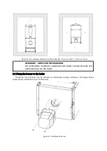
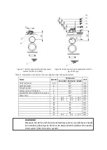


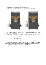


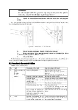

Figure 24 - The location of the controller and chokes
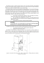
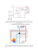
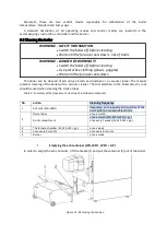
Boiler accessories should be connected in accordance with the diagram below:
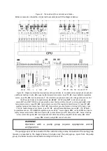
Figure 25 - Diagram of electrical connections of the controller :
λ
- Lambda probe module,
B
- module for
additional heating circuits,
BH
- upper buffer temperature sensor, type CT4,
BL
- lower buffer temperature
sensor, type CT4,
PLS
- fuel level sensor,
T
- thermostat room (make- break ),
H
- voltage output to control
the
R
reserve boiler or to signal alarms
AL
,
RELAY
- 12VDC relay,
DZT
- boiler door opening
sensor,
RP
- ecoSTER TOUCH room panel with a room thermostat function,
P
- control panel,
HW
- DHW
temperature sensor, type CT4,
M1
- temperature sensor of the regulated circuit (mixer 1), type CT4,
WS
-
weather temperature sensor, type CT6-P,
RS
- temperature sensor of water returning to the boiler, type
CT4,
FS
- feeder temperature sensor, type CT4,
OS
- optical flame brightness sensor,
BT
- CT4,
FT
boiler
temperature sensor - CT2S,
LN PE
temperature sensor, 230V ~ mains supply,
CPU
- control,
STB
-to a input o
safety temperature limiter,
FH
- main feeder,
CF
- burner blower fan,
VF
- exhaust fan,
SC
- burner cleaning
rotary motor,
IG
- igniter,
FB
- burner feeder,
CP
- DHW circulation pump,
BP
- boiler pump,
DH
- DHW
pump,
PM
- mixer 1 pump,
SM
- mixer 1 actuator.
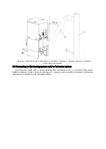
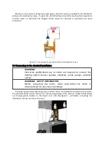
WARNING!
Operation with a pump group requires appropriate control
configuration.
The pump group must be connected to the controller using a relay. Connection of the pump group
module is presented in the diagram below. It includes only the pump group - apart from the pump
group, the boiler must be connected according to Picture nr 25 .
Summary of Contents for QUAD 10
Page 11: ......