


7
6
1. Installation Procedures
1.1 Cautions
A) Environment : This scale must be installed in a dry and liquid free environment.
B) Location : This scale must be placed on a flat and stable surface. Please keep the scale
away from oscillating fans, ventilation systems, or drafts as these air disturbances can be
picked-up by the scale and may cause incorrect weight readings.
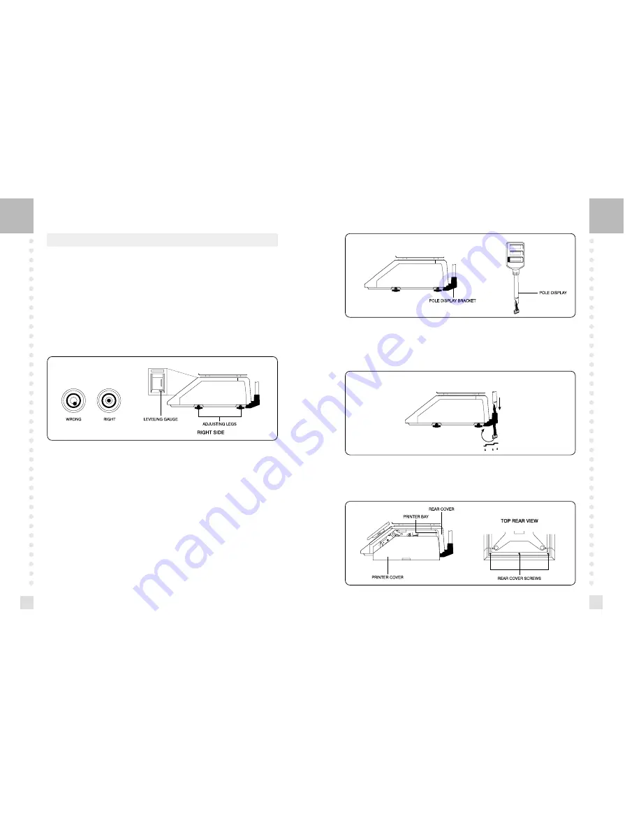
C) Leveling : If the scale is not properly level, please adjust the 4 legs at the bottom of the
scale (turn legs clockwise or counter-clockwise) so as to center the bubble of the leveling
gauge inside the indicated circle. (See below Fig.)
D) The socket-outlet shall be installed near the equipment and shall be easily accessible.
E) Danger of explosion if battery is incorrectly replaced. Replace only with the same or
equivalent type recommended by the manufacturer. Dispose of used batteries according to
the manufacturer instructions.
1.2 Assembling the Display Pole
If your scale is the “Pole” type then you must follow this section and then continue to the
next. However, if your scale is the “Non-Pole” type then you may skip this section and go on
to the next. To begin installing the Pole display, make sure your scale comes with the display
bracket & the pole display. (See below fig.)
LEVELING GAUGE
NOTE : Scale is to be used in-doors ONLY
Feed the pole display connectors down the display bracket and up through the hole in the
scale under-body. Attach the bracket cover to the display pole and then attach the bracket
cover to the bracket itself.(See below fig.)
Remove the platter from the platform. Open the printer side cover and then remove the three
rear cover screws. Feed the connectors in through the printer bay into the scale. (See below fig.)