


16
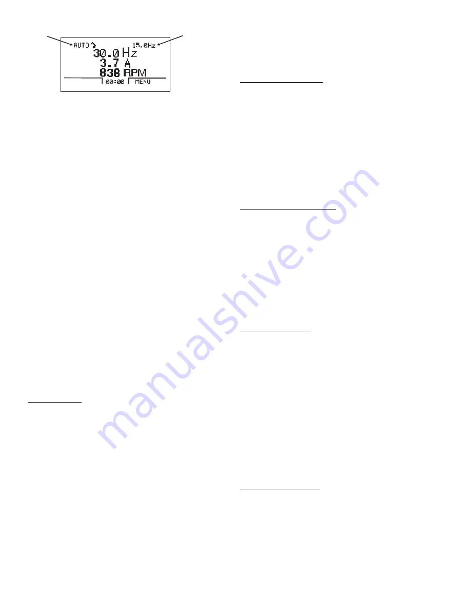
The top line of the LCD display shows the basic status
information of the drive. The HAND icon indicates that the
drive control is local from the control panel. The AUTO
icon indicates that the drive control is in remote control
mode through the I/O.
The arrow icon indicates the drive and motor rotation
status. A rotating arrow (clockwise or counterclockwise) in-
dicates that the drive is running. A rotating blinking arrow
indicates that the drive is running but not at set point.
A stationary arrow indicates that the drive is stopped. For
Carrier air handler units, the rotation is always forward.
Using parameter group 34, the middle of the LCD dis-
play can be configured to display 3 parameter values. The
default display shows parameters 0103 (OUTPUT FREQ)
in Hz, 0104 (CURRENT) in amperes, and AI1 (Analog In-
put 1) in revolutions per minute.
The upper right hand corner shows the frequency set
point that the drive will maintain. The bottom corners of the
LCD display show the functions currently assigned to the
two soft keys. The lower middle displays the current time (if
configured to show the time).
The first time the drive is powered up, it is in the OFF
mode. To switch to local hand-held control and control the
drive using the control panel, press the HAND or AUTO
buttons. Pressing the HAND button switches the drive to
hand control while keeping the drive running. Pressing the
AUTO button switches the drive to remote input control.
The OFF button stops the drive. To return to auto control,
press the AUTO button. To start the drive press the HAND
or AUTO button, to stop the drive press the OFF button.
To adjust the speed set point while in HAND mode, press
the UP or DOWN buttons (the reference changes immedi-
ately). The reference can be modified in the local control
(HAND) mode, and can be parameterized (using Group 11
reference select) to also allow modification in the remote
control mode.
Parameters Mode — The Parameters mode is used to
change the parameters on the drive. To change parameters,
perform the following procedure:
1. Select MENU (SOFT KEY 2). The Main menu will be
displayed.
2. Use the UP or DOWN keys to highlight PARAMETERS
on the display screen and press ENTER (SOFT KEY 2).
3. Use the UP or DOWN keys to highlight the desired pa-
rameter group and press SEL (SOFT KEY 2).
4. Use the UP or DOWN keys to highlight the desired pa-
rameters and press EDIT (SOFT KEY 2).
5. Use the UP or DOWN keys to change the value of the
parameters.
6. Press SAVE (SOFT KEY 2) to store the modified value.
Press CANCEL (SOFT KEY 1) to keep the previous val-
ue. Any modifications that are not saved will not be
changed.
7. Choose another parameter or press EXIT (SOFT KEY 1)
to return to the listing of parameter groups. Continue until
all parameters have been configured and then press EXIT
(SOFT KEY 1) to return to main menu.
NOTE: The current parameter value appears above the
highlight parameter. To view the default parameter value,
press the UP and DOWN keys simultaneously. To restore
the default factory settings if a drive fails, download the
parameters to the VFD from the control panel. Parameters
can also be changed individually.
Changed Parameters Mode — The Changed Parameters
mode is used to view and edit recently changed parameters
on the drive. To view the changed parameters, perform the
following procedure:
1. Select MENU (SOFT KEY 2). The Main menu will be
displayed.
2. Use the UP or DOWN keys to highlight CHANGED
PAR on the display screen and press ENTER (SOFT
KEY 2). A list of the recently changed parameters will be
displayed.
3. Use the UP or DOWN keys to highlight the desired pa-
rameter group and press EDIT (SOFT KEY 2) to change
the parameters if desired.
4. Press EXIT (SOFT KEY1) to exit the Changed Parame-
ters mode.
Drive Parameter Backup Mode — The Drive Parameter
Backup mode is used to store the drive parameters. The pa-
rameters can be uploaded from a VFD to the removable
control panel. If a drive failure occurs, the control panel can
then be transferred to the new drive and the parameters
downloaded into memory.
Each drive is custom programmed at the factory. The
first option is to download all parameters. This copies both
application and motor parameters to the drive from the con-
trol panel. This is recommended to create a backup of the
parameters group for the drive.
The second option downloads only the application pa-
rameters to the drive. Parameters 9905, 9906, 9907, 9908,
9909, 1605, 1607, 5201, and group 51 parameters and inter-
nal motor parameters are not copied.
Upload All Parameters — To upload and store all parame-
ters to the control panel from the VFD, perform the follow-
ing procedure:
1. Select MENU (SOFT KEY 2). The Main menu will be
displayed.
2. Use the UP or DOWN keys to highlight PAR BACKUP
on the display screen and press ENTER (SOFT KEY 2).
3. Use the UP or DOWN keys to highlight UPLOAD TO
PANEL and press SEL (SOFT KEY 2).
4. The text “Copying Parameters” will be displayed with a
progress indicator. To stop the process, select ABORT
(SOFT KEY 1).
5. When the upload is complete, the text “Parameter upload
successful” will be displayed.
6. The display will then return to the PAR BACKUP menu.
Select EXIT (SOFT KEY 1) to return to the main menu.
7. The control panel can now be disconnected from the
drive.
Download All Parameters — To download all parameters
from the control panel to the VFD, perform the following
procedure:
1. Install the control panel with the correct parameters onto
the replacement VFD.
2. Select MENU (SOFT KEY 2). The Main menu will be
displayed.
3. Use the UP or DOWN keys to highlight PAR BACKUP
on the display screen and press ENTER (SOFT KEY 2).
4. Use the UP or DOWN keys to highlight DOWNLOAD
TO DRIVE ALL and press SEL (SOFT KEY 2).
MODE
SET POINT
Fig. 9 — Standard Display Example
a39-2919


