background image

6

4. SETTING UP PRO- CONTROL

4.1 - General features

The interface includes different screens that are listed 
below:
• 

Default screens with direct display of the main 
parameters,

• 

Menu screens for navigation,

• 

Data/configuration screens listing the parameters by 
type,

• 

Operating mode selection screen,

• 

Password entry screen,

• 

Parameter modification screen.

NOTE: If the interface is not used for a long period, it will 
go black. The control is always active, the operating mode 
remains unchanged. The interface screen is re-animated, 
when the user presses a key. Pressing the key once illumi-
nates the screen, pressing the key a second time leads to a 
screen that is related to the context and the key symbol.

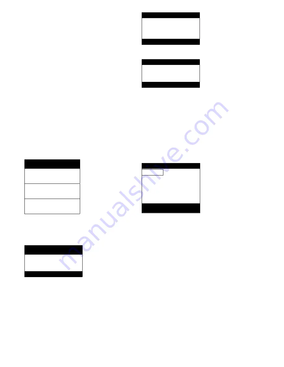
4.2 - Default screen characteristics

There are four default screens. Each screen shows:
• 

The unit status, its screen number,

• 

Three displayed parameters.

LOCAL OFF                               1

On the left the unit status, on the right 

the screen number

Entering water temp

Description of the first parameter

EWT      

40°C

Abbreviation and value with unit of 

measurement of the first parameter

Leaving water temp

Description of the second parameter

LWT

46°C

Abbreviation and value with unit of 

measurement of the second parameter

Outside air temperature

Description of the third parameter

OAT      

4°C

Abbreviation and value with unit of 

measurement of the third parameter

Pressing the Up or Down key changes one default screen 
to another default screen. The screen number is updated.

4.3 - Password screens

Enter password

Description of the password entry 

screen

      0_**

Password value

(0 = basic access)

Description

The password is entered digit by digit. The cursor is shown 
at the current digit that flashes. The arrow keys modify the 
digit value. The digit modification is validated with the 
Enter key and the cursor is moved to the next digit.

Enter password

      1_**

The first digit is 1, the cursor is 

positioned on the second digit

(0 = basic access)

Enter password

      11_**

(

0 = basic access)

Pressing the Enter key at a digit without value validates the 
overall selection of the password. The screen is refreshed 
by the menu list, and the items displayed depend on the 
level of the activated password.

The entry of an incorrect password keeps the password 
entry screen.

Password selection 0 (zero) can simply be made by pressing 
the Enter key twice in succession.

4.4 - Menu screen characteristics

\\MAINMENU

Current path in the menu structure

GENUNIT

HYDROKIT

Selection cursor to the left of the first 

column

TEMP

RUNTIME

PRESSURE

MODES

Menu list

SETPOINT

LOGOUT

INPUTS
OUTPUTS

General Parameters Menu

Description of the menu framed by 

the selection cursor

Each menu item defines the access to categorised data. The 
Up and Down arrows position the cursor at the current item. 
The Enter key activates the display of the selected sub-menu.

The item LOGOUT permits exiting from the menu screen 
and protects access by a user password. The “Previous” key 
permits exiting from the current screen without deactivating 
the password-protected access.

4.5 - Data screen or configurable parameter 

characteristics

The data screens display information parameters such as 
temperatures or pressures. The configuration screens display 
unit control parameters such as the water temperature 
setpoints.

Summary of Contents for 61AF

Page 1: ...61AF Pro Dialog Control Operating instructions MAINMENU STATUS Circuit B Total Capacity CAPB_T 0 DEM_LIM 100 SP 4 2 C CTRL_PNT 28 9 C EMSTOP dsable ENTER START STOP PRO DIALOG...

Page 2: ...2 Default screen characteristics 6 4 3 Password screens 6 4 4 Menu screen characteristics 6 4 5 Data screen or configurable parameter characteristics 6 4 6 Parameter modification 7 4 7 Operating mode...

Page 3: ...is an electronic control system to regulate units of the following types 61AF These units have only one refrigerant circuit The Pro Dialog control regulates compressor start up to control the water l...

Page 4: ...y communication via the CCN bus 3 4 The sensors Pressure sensors Two types of electronic sensors are used low pressure suction pressure and pump entering pressure optional high pressure discharge pres...

Page 5: ...X J12 Series RJ 45 series connection Pin 1 signal Pin 2 ground Pin 3 signal J2A J2B J3 J4 J12 J3 J11 J10 J9B J9A J5 J6 J7A J7B J8 J1 J2 J6 J5 J4 J9 J8 J7 3 6 2 Volt free on off contact If the unit wor...

Page 6: ...entry screen 0_ Password value 0 basic access Description The password is entered digit by digit The cursor is shown at the current digit that flashes The arrow keys modify the digit value The digit m...

Page 7: ...for the first selected character Modify value Description of the screen hsp 2 45 C Current value 46 C New value before validation Heating Setpoint 2 Item description The value is validated with the En...

Page 8: ...emperatures Pressures Setpoint Inputs Outputs Unit status Operating time Language selection Alarm menu Configuration menu Disconnection Reset of the alarms Current alarms Alarm history Time schedule H...

Page 9: ...N mode and this override value will have priority over the other limit values external or limit control 8 Control point This point can be forced in CCN mode and this override value will have priority...

Page 10: ...sor A2 st_cp_a2 nnnnn Number of start ups compressor A2 hr_fana1l nnnnn hours Number of low speed operating hours fan A1 hr_fana1h nnnnn hours Number of high speed operating hours fan A1 hr_fana2l nnn...

Page 11: ...off time schedule OCC1P02S Unit setpoint selection time schedule 4 9 15 HOLIDAY menu NAME DESCRIPTION HOLDY_01 Holiday period 1 HOLDY_02 Holiday period 2 HOLDY_03 Holiday period 3 HOLDY_04 Holiday pe...

Page 12: ...start up of the first electric heater stage ehs_defr Yes No No Quick electric heat stages for defrost 4 9 20 RESETCFG menu NAME FORMAT DEFAULT UNIT DESCRIPTION oathr_non 10 to 51 7 10 C Outside tempe...

Page 13: ...ive on the same day the occupied mode takes priority over the unoccupied period Each of the eight periods can be displayed and changed with the aid of a sub sub menu The following table shows how to a...

Page 14: ...Wednesday Thursday Friday Saturday Sunday Holiday OCCTOD6 0 00 24 00 00 00 Occupied from UNOCTOD6 0 00 24 00 00 00 Occupied until DOW7 0 1 0 Period 7 days of the week MTWTFSSH Monday Tuesday Wednesda...

Page 15: ...Off Active Unoccupied Remote Off Active Open Remote Remote Off Active Remote Unoccupied Remote Off Active Closed Occupied Disabled No Remote On Active Closed Remote Occupied Disabled No Remote On 5 2...

Page 16: ...ion of compressor starts which makes leaving water temperature control less precise In addition the high pressure low pressure or defrost unloading functions can also affect the temperature control ac...

Page 17: ...CCN bus All parameters required for the master slave function must be configured through the Service configura tion menu Master slave operation requires the connection of a tempe rature probe at the c...

Page 18: ...ctions The local interface and its various menus give access to all unit operating conditions If an operating fault is detected an alarm is activated and an alarm code is stored in the Alarms menu sub...

Page 19: ...01 Water heat exchanger frost protection Automatic if the same alarm has not tripped during the last 24 hours otherwise manual Water flow rate too low or defective thermistor Unit is shut down 19 P 05...

Page 20: ...arm No Alarm code Alarm description Reset type Probable cause Action taken by the control Process faults continued 37 FC nn Illegal factory configuration number Manual The unit size has been configure...

Reviews: