background image

3. Working from furnace to outside, cut pipe to required

length(s).

4. Deburr inside and outside of pipe.

5. Chamfer outside edge of pipe for better distribution of primer

and cement.

6. Clean and dry all surfaces to be joined.

7. Check dry fit of pipe and mark insertion depth on pipe.

8. After pipes have been cut and preassembled, apply generous

layer of cement primer to pipe fitting socket and end of pipe
to insertion mark. Quickly apply approved cement to end of
pipe and fitting socket (over primer). Apply cement in light,
uniform coat on inside of socket to prevent buildup of excess
cement. Apply second coat.

9. While the cement is still wet, twist pipe into socket with a

1/4-turn. Be sure pipe is fully inserted into fitting socket.

10. Wipe excess cement from joint. A continuous bead of cement

will be visible around the perimeter of a properly made joint.

11. Handle pipe joints carefully until cement sets.

12. Support piping at minimum of every 5 ft (3 ft for SDR-21 or

-26 PVC) using perforated metal hanging strap. Slope
combustion-air and vent pipes toward furnace a minimum of
1/4 in. per linear ft with no sags between hangers.

13. Use appropriate methods to seal openings where vent and

combustion-air pipes pass through roof or side wall.

Step 8—Vent Terminal Kit Installation

The combustion-air and vent pipes must terminate outside the
structure. A factory-supplied terminal kit must be installed as in 1
of the installations shown in Fig. 6 or 7. A roof termination is
preferred. The combustion-air inlet fitting is the factory-provided
elbow with air splitter. (See Fig. 7.)

1. Roof termination is preferred. (See Fig. 7.)

a. Inlet of combustion-air pipe must terminate no less than 12

in. above roof or snow accumulation level.

b. Inlet of combustion-air pipe must terminate 12 in. away

from vertical wall or other protrusion.

2. Termination through existing chimney may be used provided:

a. No other gas-fired or wood-burning appliance is vented

into chimney.

b. Both combustion-air and vent pipes run entire length of

chimney.

c. Top of chimney is sealed and weatherproofed.

3. Sidewall termination. (See Fig. 6.)

a. Terminations must be made 12 in. above anticipated annual

snow accumulation level or grade, whichever is greater.

b. Minimum of 4 ft clearance must be provided from electric

or gas meters, regulators, and relief equipment.

4. Install 90° elbows as shown in Fig. 6 or 7, or use a 180°

U-fitting.

5. Install tee as shown in Fig. 6 or 7.

6. Check required dimensions as shown in Fig. 6 or 7.

7. Disassemble loose pipe fittings. Clean and cement fittings

using same procedures as outlined for system piping.

8. Secure combustion-air and vent pipe terminations with

Z-shaped termination bracket (provided).

MULTIVENTING AND VENT TERMINATIONS OF 58EJB
FURNACES — When 2 or more 58EJB Furnaces are vented near
each other, each furnace must be individually vented. Never
common vent or breach-vent these furnaces. There must be a
12-in. separation between the combustion-air and vent pipes of the
first and second furnaces. The next vent termination must be at
least 4 ft away from the first 2 terminations. It is important that the
vent terminations be constructed in this manner to avoid recircu-
lation of flue gases.

Step 9—Condensate Drainage

This furnace must use the condensate trap supplied with the unit.
See Fig. 9 for proper drain installation. The drain must terminate
at a floor drain, sewer system, or drain vent for proper condensate
removal. Drain installation must conform with local building
codes. For proper condensate drainage from the furnace, the
furnace MUST be within 1/2 in. of level. That is, the highest corner
of the furnace must not be more than 1/2 in. higher than the lowest
corner.

NOTE:

The condensate trap MUST be connected to the PVC tee

on the drain line exiting the unit as shown in Fig. 9. Failure to
place the trap at this location may cause erratic unit operation and
nuisance furnace shutdown.

The 1/2-in. diameter schedule-40 PVC or CPVC condensate drain
piping and pipe fittings must conform to ANSI standards and
ASTM D1785 or D2846. The schedule-40 PVC or CPVC cement
and primer must conform to ASTM D2564 or F493.

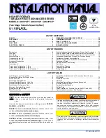
Fig. 8—Combustion-Air Piping

A91215

AIR INLET

PIPE

DO NOT SEAL

THIS JOINT

COMBUSTION-AIR INLET PLATE

In all installations the
combustion-air inlet
piping must be connected
with an elbow pointing up
to allow access to the
burner assembly.

NOTE:

Fig. 9—Condensate Drain System

A91176

1

INDUCER
HOUSING
TUBE

VENT DRAIN

TUBE

TO VENT

TERMINATION

Connect to approved
sewer system per these
instructions and local
codes.

NOTE:

8

Summary of Contents for 101 Series

Page 1: ...ther than wood The design of this furnace line is not A G A certified for installation in recreational vehicles manufactured housing mobile homes or outdoors Before installing this furnace refer to the current edition of the NFGC NFPA 54 1992 ANSI Z223 1 1992 which is available from the National Fire Protection Association Inc Batterymarch Park Quincy MA 02269 American Gas Association 1515 Wilson ...

Page 2: ...n UNIT SIZE 050 075 100 AND 125 Sides 0 Back 0 Top of Plenum 0 Vent Connector PVC Pipe 0 Front Casing 1 Front Service 30 Zero in with controls on front of furnace 1 in from back of elbow with combustion air inlet on back of furnace and 1 in from end of inducer motor with controls located on back of furnace Measured from end of inducer motor Table 2 Dimensions In UNIT SIZE LENGTH WIDTH WEIGHT LB 05...

Page 3: ...TION RELATIVE TO COOLING EQUIP MENT The cooling coil must be installed parallel with or on the downstream side of the furnace to avoid condensation in the heat exchanger When installed parallel with a furnace dampers or other means used to control the flow of air must prevent chilled air from entering the furnace If the dampers are manually operated they must be equipped with a means to prevent op...

Page 4: ... with appropriate straps hangers etc Use a minimum of 1 hanger every 6 ft Joint compounds pipe dope should be applied sparingly and only to the male threads of the joints This pipe dope must be resistant to the action of propane gas Install a sediment trap in the riser leading to the furnace The trap can be installed by connecting a tee to the riser leading to the furnace so that the straight thro...

Page 5: ...4 V WIRING Make field 24 v connections at the 24 v termi nal block Connect Y terminal as shown in Fig 4 for proper cooling operation The 24 v terminal board is marked for easy connection of field wiring See Fig 5 NOTE Use AWG No 18 color coded copper thermostat wire for lengths up to 100 ft For wire lengths over 100 ft use AWG No 16 wire ACCESSORIES Install accessories per manufacturer s instruc t...

Page 6: ...Standards COMBUSTION AIR AND VENT PIPING The combustion air and vent pipe fittings must conform to American National Standards Institute ANSI standards and American Society for Testing and Materials ASTM standards D1785 schedule 40 PVC D2665 PVC DWV D2241 SDR 21 and SDR 26 PVC D2661 ABS DWV or F628 schedule 40 ABS Pipe cement and primer must conform to ASTM standards D2564 PVC or D2235 ABS See Tab...

Page 7: ...ing such as when it passes through an unheated space or when a chimney is used as a raceway the pipe must be insulated with 1 2 in thick Armaflex type insulation When the combustion air pipe is installed above a suspended ceiling the pipe must be insulated with 1 2 in Armaflex type insulation The combustion air pipe should also be insulated when it passes through a warm humid space Solvent cements...

Page 8: ...lation level or grade whichever is greater b Minimum of 4 ft clearance must be provided from electric or gas meters regulators and relief equipment 4 Install 90 elbows as shown in Fig 6 or 7 or use a 180 U fitting 5 Install tee as shown in Fig 6 or 7 6 Check required dimensions as shown in Fig 6 or 7 7 Disassemble loose pipe fittings Clean and cement fittings using same procedures as outlined for ...

Page 9: ...ield reversal be sure to have a correct wiring diagram available and be prepared to mark all wires as they are disconnected The inducer assembly burner controls gas valve and electrical controls are designed to be field reversed as necessary for certain field installations and applications per the following procedure 1 Remove manifold cover plate and air inlet plate burner re moval cover 2 Disconn...

Page 10: ...all vent return pipe so pipe outlet is facing rear of unit Reinstall 4 washers and nuts securing pipe to heat exchanger bottom plate Remove and discard cardboard previously placed between fins and pipe Remove patch plate and cut insulation on rear center panel and position vent return pipe through panel Secure pipe to panel with 4 screws 30 Remove blower motor wiring harness strain relief from fro...

Page 11: ...umper wire on pressure switches 11 Turn on gas valve 12 Turn on electrical supply to unit Unit should begin ignition cycle Step 11 Start up Adjustment and Safety Check GENERAL The furnace must have a 115 v power supply properly connected and grounded Proper polarity must be main tained for correct operation Thermostat wire connections at R W Y G and C must be made at the 24 v terminal block on the...

Page 12: ... 34 35 36 3 2 3 3 3 7 890 38 39 3 4 3 7 37 38 39 3 2 3 5 3 8 37 38 3 3 3 6 37 38 3 4 3 8 36 37 3 2 3 5 36 37 3 3 3 6 36 37 3 4 3 7 36 3 5 35 36 3 2 3 6 905 38 39 40 3 3 3 6 3 8 38 39 3 4 3 7 37 38 39 3 2 3 5 3 8 37 38 3 3 3 6 37 38 3 4 3 8 36 37 3 2 3 5 36 37 3 3 3 6 36 37 3 4 3 7 36 37 3 5 3 8 920 38 39 40 3 2 3 4 3 7 38 39 40 3 3 3 6 3 8 38 39 3 4 3 7 37 38 39 3 2 3 5 3 8 37 38 3 3 3 6 37 38 3 4...

Page 13: ... pressure item c and replace the main burner orifices as needed Refer to NFGC Appendix F Table F 4 for proper orifice sizing at high altitudes 8 Proceed to item c to adjust manifold pressure c Adjust gas input NOTE The gas meter must always be clocked with the burner enclosure front installed The gas valve has been nominally set at 3 5 in wc for natural gas 1 Remove burner enclosure front and cap ...

Page 14: ...selector located at the blower motor See Table 10 Table 10 Blower Speed Selection SPEED TAP NO Common 1 High 2 Medium 3 Low 4 Recheck the temperature rise It must be within limits specified on the unit rating plate Recommended operation is at midpoint of rise or above 3 Set thermostat heat anticipator The thermostat heat anticipator must be set to match the amp draw of the components in the R to W...

Page 15: ...drain safety switch This control ensures the condensate drain is open to allow condensate flow and that combustion air is flowing through the unit prior to starting the ignition cycle The blocked drain safety switch has only 1 tube connected to it Check switch operation as follows a Place unit into operation with burners on b Pinch off tube leading to pressure switch P2 The burners should shut off...

Page 16: ...D DISCONNECT ON HOT LEG 1 2 3 4 60 SEC 90 SEC 120 SEC DELAY OFF SCREW SETTINGS 150 SEC MED HI GND N2 HEAT COOL N3 D1 N4 C BI S1 S2 M2 K1 K2 K2 K3 X R Y C W G CN23 2 CN23 1 CN23 6 LIMIT CONTROL TRANSFORMER CONDENSING UNIT PRESSURE SW N O N C PS1 PS2 V1 CN23 3 CN23 5 COM ST912081005 ELECTRONIC FAN TIMER ROS MV PV MV PV MV MV PV PV 24V GNO GNO BURNER SPARK GAS VALVE HONEYWELL VR8204 PILOT 24V IGNITIO...

Reviews: