


6-21
T-294-01
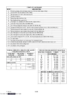
RRS or SRS:
Using the plug connector marked “EC” that is
connected to the Controller module. Locate the wires
marked RRS or SRS, depending on which sensor needs
to be replaced. Follow that wire to the connector and
using the pins of the plug, measure the ohms resistance.
Readings are shown in Table 6-5.
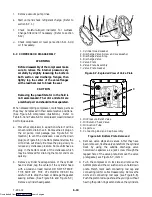
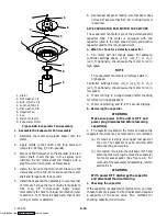
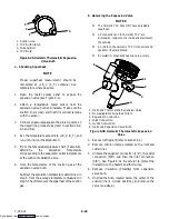
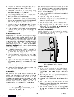
6.23.2 Replacing Sensor (STS and SRS)
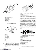
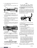
To properly position a unit supply sensor, the sensor
must be fully inserted into the probe holder. This
positioning will give the sensor the optimum amount of
exposure to the supply air stream, and will allow the
Controller to operate correctly. Insufficient probe
insertion into the probe holder will result in poor
temperature control due to the lack of air flow over the
sensor.
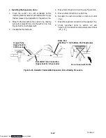
It is also necessary to ensure that the probe tip does not
contact the evaporator back panel. The design minimum
clearance of 6 mm (1/4 inch) should be maintained (see
Figure 6-21).
Cap and Grommet
Assembly
Probe
Holder
Supply Sensor
Sensor
Wires
Supply
Air
Stream
Evaporator
Back Panel
6 mm
(1/4 inch)
Figure 6-21. Supply Sensor Positioning
a. Turn unit power OFF and disconnect power supply.
b. Remove and save any cover (if present) over wiring
and probe holder.
c. Cut cable 5 cm (2 inches) from shoulder of defective
sensor and discard the defective probe only. Save
cap and grommet assembly for reuse on the
replacement probe.
Do not cut the grommet.
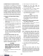
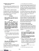
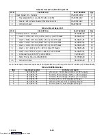
d. Cut one wire of existing cable 41 mm (1-5/8 inches)
shorter than the other wire.
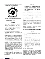
e. Cut one replacement sensor wire (opposite color)
back 41 mm (1-5/8 inches). (See Figure 6-22.)
Sensor
41 mm (1-5/8 inches)
6.35 mm (1/4 inch)
Figure 6-22. Sensor (RRS, RTS, SRS or STS)
f. Strip back insulation on all wiring 6.35 mm (1/4
inch).
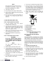
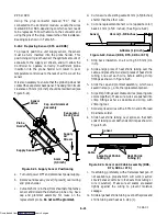
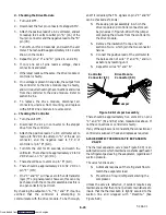
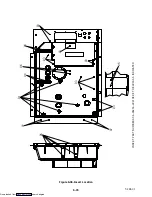
g. Slide a large piece of heat shrink tubing over the
cable, and place the two small pieces of heat shrink
tubing, one over each wire, before adding crimp
fittings as shown in Figure 6-23.
h. Slide the cap and grommet assembly, which was
saved in step (c.), onto the replacement sensor.
i. Slip crimp fittings over dressed wires (keeping wire
colors together). Make sure wires are pushed into
crimp fittings as far as possible and crimp with
crimping tool.
j. Solder spliced wires with a 60% tin and 40% lead
Rosincore solder.
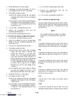
k. Slide heat shrink tubing over splice so that both
ends of tubing cover both ends of crimp as shown in
Figure 6-23.
Sensor
Cable
Heat Shrink
Tubing (2)
Large Heat Shrink
Tubing (1)
Figure 6-23. Sensor and Cable Assembly (RRS,
RTS, SRS or STS)
l. Heat tubing, preferably with a flameless heat gun. If
not available, a propane torch will work
(caution
should be taken not to burn the heat shrink tubing or
wire insulation
). Make sure all seams are sealed
tightly against the wiring to prevent moisture
seepage.
m. Slide large heat shrink tubing over both splices and
shrink tubing and heat as in step (l.).
Downloaded from


