


2-11
T-294-01
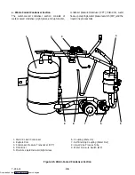
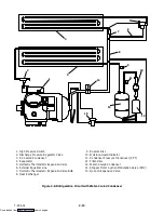
2.5 REFRIGERATION CIRCUIT WITH THE
WATER-COOLED CONDENSER
Starting at the compressor, the suction gas is
compressed to a higher temperature and pressure.
When operating with the water-cooled condenser, the
gas flows through the discharge line into the pressure
regulator valve that is normally open. The pressure
regulator valve may restrict the flow of refrigerant to
maintain a minimum discharge pressure of 5 kg/cm
2
(70
psig).
Refrigerant gas then moves through the air-cooled coil
to the water-cooled condenser. As the refrigerant flows
across the water chilled coiled tube bundle, it is cooled
to saturation temperature and exits the condenser as a
high pressure/saturated liquid.
From the water-cooled condenser, the liquid refrigerant
continues through the filter-drier (which keeps
refrigerant clean and dry), and a heat exchanger that
increases subcooling of liquid refrigerant to the
thermostatic expansion valve. As the liquid refrigerant
passes through the orifice of the hermetic expansion
valve, some of it vaporizes into a gas (flash gas). Heat is
absorbed from the return air by the balance of the liquid,
causing it to vaporize in the evaporator coil. The vapor
then flows through the stepper motor suction
modulation valve to the compressor.
The hermetic thermostatic expansion valve bulb (on the
suction line near the evaporator coil outlet) controls the
expansion valve, maintaining a constant superheat at
the coil outlet regardless of load conditions.
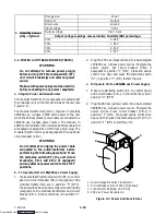
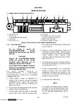
2.6 WATER-COOLED CONDENSER
The water-cooled condenser is used when cooling water
is available and heating the surrounding air is
objectionable, such as in a ship’s hold.
The water-cooled condenser is of the shell and coil type,
with water circulating through the cupro-nickel coil.
The refrigerant vapor is admitted to the shell side and is
condensed on the outer surface of the coil.
2.6.1
Water--Cooled Condenser with Water
Pressure Switch (WP)
For operation of the refrigeration unit with the
water-cooled condenser, perform the following:
a. Connect the water supply line to the inlet side of
condenser and the discharge line to the outlet side of
the condenser.
b. Maintain a flow rate of 11 to 26 liters per minute (3
to 7 gallons per minute). The water pressure switch
will open to de-energize the condenser fan relay,
unless overridden by the out-of-range lockout
feature (if so equipped). The condenser fan motor
will stop and will remain stopped until the water
pressure switch closes, or it is overridden by the
out-of-range lockout feature (if so equipped).
The refrigeration unit operating with the water-cooled
condenser will perform as outlined in section 4.4 except
that the condenser fan motor may be stopped in all
modes.
To shift to air-cooled condenser operation, perform the
following:
Disconnect the water supply and the discharge line to
the water-cooled condenser. The refrigeration unit will
shift to air-cooled condenser operation when the water
pressure switch closes. (Refer to section 2.2.)
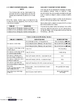
2.6.2
Water-Cooled Condenser with Condenser
Fan Switch (CFS) -- Optional
For operation of the refrigeration unit with the
water-cooled condenser with (CFS), perform the
following:
a. Connect the water supply line to the inlet side of
condenser and the discharge line to the outlet side of
the condenser.
b. Maintain a flow rate of 11 to 26 lpm (3 to 7 gpm).
c. Set CFS switch to position ”O” when water is
supplied to the water-cooled condenser. This will
de-energize the condenser fan relay. The condenser
fan motor will stop and will remain stopped until
the CFS switch is set to position ”1.”
The refrigeration unit operating with the water-cooled
condenser and the CFS switch in position ”O,” will
perform as outlined in section 4.4 except that the
condenser fan motor is stopped in all modes.
WARNING
When water flow is below 11 lpm (3 gpm) or
when water-cooled operation is not in use,
the CFS switch MUST be set to position ”1”
or the unit will not operate properly.
To shift to air-cooled condenser operation, perform the
following:
Turn the unit OFF and set the CFS switch to position
”1.” Disconnect the water supply and the discharge line
to the water-cooled condenser. The unit should now
perform as outlined in section 4.4.
Downloaded from


