3-15
T-294-01
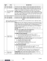
The supply probe is used for control and is so indicated
by the “SUPPLY” LED on the display module. The
Perishable temperature range demands high accuracy.
The unit is capable of maintaining supply air
temperature to within
¦
0.25
_
C (
¦
0.5
_
F) of the set
point temperature setting. In Perishable range
above
--10
_
C (+14
_
F),
or --5
_
C (+23
_
F) optionally, control is
maintained by controlling the position of the stepper
motor suction modulation valve (SMV) with the
compressor energized.
When pulling down from a control temperature that is
more than 5
_
C (9
_
F) above set point, the SMV valve
will be open to reduce the pulldown time. The pressure
and current limit functions may restrict the valve, if the
pressure or current is above the selected value.
When the controlling probe temperature enters the
in-range temperature tolerance as selected at function
code Cd30, the in-range light will energize.
The Controller logic is designed so the SMV will begin
to close as the set point is reached. The SMV will close
to restrict refrigerant flow until the capacity of the unit
and the load are balanced, unless the compressor
reliability enhancement logic on the first compressor
start prevents closure.
If the temperature drops below the set point, the
compressor will remain running for a few minutes. This
is to accommodate any initial undershoot which might
occur. After this time, and at 0.2
_
C (0.4
_
F) or greater
below the set point, the compressor will be turned OFF.
The heaters will be energized if the temperature drops to
0.5
_
C (0.9
_
F) below the set point. The heaters will
de-energize when the temperature rises to 0.2
_
C
(0.4
_
F) below the set point. The compressor will not
restart until the temperature rises to 0.2
_
C (0.4
_
F)
above the set point and a three minute time delay since
the last compressor turn off has been satisfied.
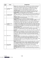
b. Operation in the dehumidification mode
(Code 33 value selected) -- Optional
The dehumidification mode is activated by selecting
Code 33, choosing a desired relative humidity value,
and pressing the ENTER key. The control probe LED
(supply 1) will flash ON and OFF every second to
indicate that the dehumidification mode is active. Once
the Mode is active and the following conditions are
satisfied, the Controller will activate the heat relay to
begin dehumidification.
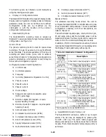
1. The humidity sensor reading is above the set point
and valid (AL67).
2. The pulldown mode is NOT active. (ie., The
control temperature is less than 5
_
C above set
point.)
3. The control probe (i.e.; Supply 1) temperature is
less than set point, plus 0.25
_
C.
4. Temperature control set point is greater than
--10
_
C
(+14
_
F),
or --5
_
C (+23
_
F) optionally, in the
perishable range, and the compressor is running.
5. The heater debounce timer (three minutes) has
timed out.
6. Heat termination thermostat (HTT) is closed.
7. The Controlled Atmosphere (CA) option VENT or
Pre-Trip mode is not initiated.
8. Humidity sensor alarm is not active (AL67).
9. High pressure switch (HPS) is not open.
If the above conditions remain true for at least one hour
the evaporator fans will switch from high to low speed
operation (on units so equipped). The evaporator fan
speed will switch every hour thereafter as long as all
conditions are met (see Bulb Mode section for different
evaporator fan speed options). If any condition except
for item (1.) becomes false OR if the relative humidity
sensed is 2% below the dehumidification set point, the
high speed evaporator fans will be energized.
The dehumidification mode applies power to the defrost
and drain pan heaters. This added heat load causes the
Controller to open the modulating valve to match the
new total heat load while still holding the supply air
temperature very close to the set point.
Opening the modulating valve reduces the temperature
of the evaporator coil surface, which increases the rate at
which water is condensed from the air passing through
the coil. Removing water from the air reduces the
relative humidity. When the relative humidity sensed is
2% below the set point (function code Cd33), the
Controller de-energizes the heat relay. The Controller
will continue to cycle heating to maintain relative
humidity below the selected set point.
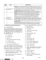
Two timers are provided in the Dehumidification mode
to prevent rapid mode switching and consequent
contactor wear. They are:
S
Heater debounce timer (three minutes).
S
Out-of-range timer (five minutes).
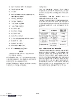
The heater debounce timer is activated whenever the
heater contactor status is changed. The heat contactor
remains energized (or de-energized) for at least three
minutes even if the set point criteria are satisfied. This is
Downloaded from

