


6-4
T-294-01
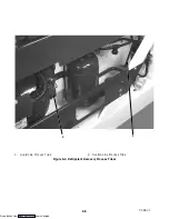
6.4 REFRIGERANT RECOVERY
1. Disconnect the tube clamp connected to the baffle
plate on the liquid line process tube. Remove the
baffle plates covering both process tubes.
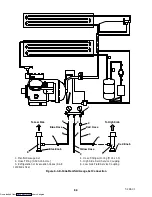
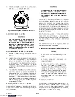
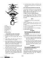
2. Install the piercing valve (refer to section 6.2) on the
liquid line process tube and the suction line process
tubes (see Figure 6-4). The valve should be
installed as close as possible to the pinched-off end
of the liquid line and suction line process tubes.
Make sure the tubing is a full round diameter.
3. Install the 3/8 to 1/4 inch adapter to the1/4 inch flare
fitting on the piercing valves. Connect the high side
and low side of the R-134a manifold gauge set to the
3/8 inch hose fittings.
4. Connect the refrigerant recovery unit to the center
hose on the manifold gauge set. Close the piercing
valves, rotating the valve stems fully clockwise.
Following the instructions for your refrigerant
recovery unit start up and open the piercing valves
at the appropriate time by turning the valve stems
counter-clock wise.
5. When the refrigerant is fully recovered from the
system, remove the refrigerant recovery unit. Using
dry nitrogen break the vacuum and bring the system
pressure to a slightly positive pressure of 2 to 5 psig.
6. Remove any positive pressure from the system
through the manifold gauge set and leave the
piercing valve open and the gauge set center hose
open to prevent any pressure build-up in the
refrigeration system.
WARNING
Before proceeding with the repair make
certain that the stepper motor suction
modulation valve (SMV) is open (refer to
section 6.24) and that there is no positive
pressure in the system.
7. To reduce the time required for evacuation,
dehydration and refrigerant charging of the system,
perform the following steps.
S
Remove the piercing valves from the liquid
line and suction line process tubes.
S
Using the tubing cutter, cut the process tubes
below the pierced hole in liquid line and
suction line process tubes.
S
Place the 3/8 inch flare nuts on both process
tubes and flare the tube.
S
Connect the 3/8 inch to 1/4 inch flare adapter
and
the 1/4 inch
swivel elbow x R-134a
refrigerant adapter to the R-134a gauge set.
The refrigeration unit is now ready for repair, and/or
component replacement, refer to sections 6.6 and 6.7.
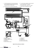
8. Pressurize the system with nitrogen and R-134a,
and leak test the entire system.
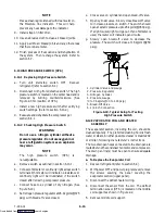
9. Connect the vacuum pump to the center hose on the
manifold gauge set, and thoroughly evacuate the
system to 500 microns.
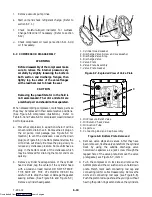
10. Charge the system with the correct weight (refer to
unit model plate, see Figure 2-1 for location) of
refrigerant R-134a using an accurate weight scale.
11. Run test the unit.
When it is determined that the unit is performing
normally, the unit should be sealed to its original
hermetic state as explained below.
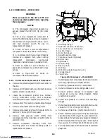
12. Use the process tube pinch-off tool to seal the tubes
before the 3/8 inch flare assembly (one tube at a
time, if necessary).
13. Vent the line to the gauge set and tighten. Check for
refrigerant leaks after the pinch-off tool, monitor
the gauge set for a pressure rise. If there is a pressure
rise, tighten the pinch-off tool until there is no
pressure rise at the gauge set.
14. Leave the pinch-off tool in place, and remove the
fittings from the liquid line or suction line process
tube.
WARNING
Do not remove the pinch-off tool from the
process tubes until the following procedures
are completed.
15. Using the tubing cutter, cut-off the excess tubing as
close to the pinch-off tool as possible.
16. Use an oxyacetylene torch to braze the exposed end
of the process tubes.
17. Remove the pinch-off tool and leak test the process
tubes at the brazed end.
18. Install both baffle plates, then connect the tube
clamp to the baffle plate on the liquid line process
tube.
Downloaded from


