


6-7
T-294-01
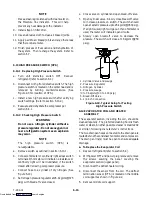
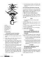
refrigerant container on weight scales. The correct
amount of refrigerant may be added by observing
the scales. (Refer to section 6.7)
6.7 REFRIGERANT CHARGE
6.7.1
Checking the Refrigerant Charge
NOTE
To avoid damage to the earth’s ozone layer, use
a refrigerant recovery system whenever
removing refrigerant. When working with
refrigerants you must comply with all local
government environmental laws. In the U.S.A.,
refer to EPA section 608.
NOTE
Set the controller set point to --25
_
C (--13
_
F) to
ensure that the suction modulation valve is
fully open when checking operation of unit.
The
container
temperature
should
be
approximately 1.7
_
C (35
_
F) or --17.8
_
C (0
_
F).
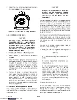
a. Connect the gauge manifold to line piercing valves,
refer to sections 6.2, 6.3 and 6.4.
b. Check charge only on air-cooled operation. Refer to
Figure 6-37 for charts on compressor pressure.
c. If the discharge/suction pressures are within the
normal operating system pressures, then the charge
should be correct.
d. If the discharge/suction pressures are NOT within
the normal operating system pressures, then refer to
sections 5.2, 5.3, 5.7 and 5.11 for possible causes. If
the unit is then determined to be low on refrigerant
charge, refer to section 6.7.2 or 6.7.3.
6.7.2
Adding Refrigerant to System (Full Charge)
a. Evacuate unit and leave in deep vacuum. (Refer to
section 6.6.)
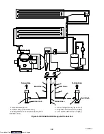
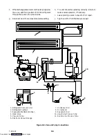
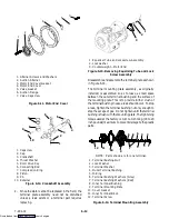
b. Place cylinder of R-134a on scale and connect
charging line from cylinder to the liquid line
process tube. Purge charging line at liquid line and
then note weight of cylinder and refrigerant.
c. Open liquid valve on cylinder. Open liquid line
half-way and allow the liquid refrigerant to flow
into the unit until the correct weight of refrigerant
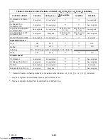
has been added as indicated by scales. Correct
charge is noted in Table 6-9.
NOTE
It may be necessary to finish charging the unit
through the suction line process tube in gas
form, due to pressure rise in high side of the
system. (Refer to section 6.7.3)
d. Backseat the manifold gauge port. Close liquid
valve on cylinder.
e. Start unit in cooling mode. Run approximately 10
minutes and check the refrigerant charge. (Refer to
section 6.7.1.)
6.7.3
Adding Refrigerant to System (Partial
Charge)
a. Examine the unit refrigerant system for any
evidence of leaks. Repair as necessary. (Refer to
section 6.5.)
b. Maintain the conditions outlined in section 6.7.1.
c. Fully backseat the manifold gauge port.
d. Connect charging line between the suction line
process tube and the cylinder of refrigerant R-134a.
Open VAPOR valve.
e. Partially frontseat (turn clockwise) the manifold
gauge valve and slowly add charge until the
refrigerant appears at the proper level (refer to
section 6.7.1).
6.7.4
Emergency
Shipboard
Refrigerant
Charging Procedure
If the unit is not maintaining set point, refer to sections
5.2, 5.7 and 5.11 for possible causes. If the unit is then
determined to be low on refrigerant charge, follow the
steps below.
a. Perform step 6.7.1.a.
b. If the unit is operating on water-cooled condenser
switch to air-cooled condenser operation, refer to
section 2.6.1.
c. If set point is in a perishable range, temporarily
lower the unit set point to ensure that the SMV is
fully open for this procedure.
CAUTION
Make sure supply air temperature does not
go below the original set point for more than
five minutes, or damage to the load may
occur.
d. Refer to the pressure temperature curves in
Figure 6-37.
e. If the discharge/suction pressures are within the
normal operating system pressures, then the charge
should be correct.
Downloaded from


