


6-30
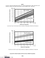
T-294-01
5. Press the ENTER key on the keypad.
6. The Display will show the message “Pro SoFt.”
This message will last for up to one minute.
7. The Display module will read:
(a.) When the software loading has successfully
completed: the Display will show the message
“Pro donE.”
(b.) If a problem occurs while loading the software:
the Display will blink the message “Pro FAIL”
or “bad 12V.” (Turn start-stop switch OFF and
remove the card.)
8. Turn unit OFF, via start-stop switch (ST).
9. Remove the programming card from the
programming/software port.
10. Turn unit ON, via start-stop switch (ST).
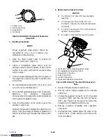
b. Procedure for loading Configuration Software
1. Turn unit OFF using start-stop switch (ST).
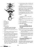
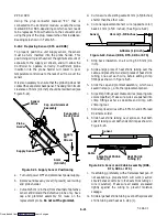
2. Insert the programming card, for Configuration
Software, into the programming/software port.
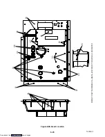
(See Figure 6-32.)
3. Turn unit ON using start-stop switch (ST).
4. The Display module will read:
(a.) If the correct card is being used, the digital
display will show “nt40” on the left LCD
display and “511XXX” on the right LCD
display. “XXX” will indicate the dash number
for a given unit model number, use the UP or
DOWN ARROW key to scroll through the list
to obtain the proper model dash number (i.e.,
For the unit 69NT40-511-201, the left display
will show “nt40,” press the UP or DOWN
ARROW key until the right display shows
“511201.”)
(b.) If a defective card is being used, the Display
will blink the message “bAd CArd.” (Turn
start-stop switch OFF and remove the card.)
5. Press the ENTER key on the keypad.
6. The Display module will read:
(a.) When the software loading has successfully
completed, the Display will show the message
“EEPrM donE.”
(b.) If a problem occurs while loading the software,
the Display will blink the message “Pro FAIL”
or “bad 12V.” Turn start-stop switch OFF and
remove the card.
7. Turn unit OFF using start-stop switch (ST).
8. Remove the programming card from the
programming/software port.
9. Turn unit ON using start-stop switch (ST).
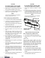
6.27.2 Controller Trouble-Shooting
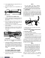
A group of test points (tp) are provided on the Controller
(see Figure 6-32, item 3) for trouble-shooting electrical
circuits (refer to section 5). A description of the test
points follows:
NOTE
Use a digital voltmeter to measure ac voltage
between TP’s and ground (TP9), except for
TP8.
TP2
This test point enables the user to check if the internal
protector for the compressor motor (IP-CP) is open or
closed (and the Auto Transformer-IP if so equipped).
TP3
This test point enables the user to check if the optional
water pressure switch (WP) contact is open or closed.
TP 4
This test point enables the user to check if the internal
protector for the condenser fan motor (IP-CM) is open
or closed.
TP 5
This test point enables the user to check if the internal
protectors for the evaporator fan motor (IP-EM1 or
IP-EM2) is open or closed.
TP 9
This test point is the chassis (unit frame) ground
connection.
TP 10
This test point enables the user to check if the heat
termination thermostat (HTT) contact is open or closed.
Downloaded from


