background image

2-1

T-294-01

SECTION 2

DESCRIPTION

2.1 GENERAL DESCRIPTION

a. Refrigeration Unit -- Front Section

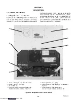
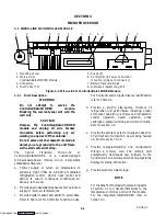
The front section of the refrigeration unit shows access
to most parts of the unit (i.e., compressor, condenser,
receiver, etc.), which will be discussed in more detail of

the following sections in 2.1. The upper access panels
allow front entry into the evaporator section, and the

center access panel allows access to the evaporator coil
heaters. The unit model number, serial number and
parts identification number will be found on the front of
the unit to the left of the compressor.

1

2

3

4

5

6

7

1. Access Panel (For Evap. Fan Motor #1)

2. Access Panel (For Heater)

3. Fork Lift Pockets

4. Unit Serial Number, Model Number and

Parts Identification Number (PID) Plate

5. Interrogator Connector (IC)

6. Lower Fresh Air Makeup Vent or Blank Plate --

Optional

7. Upper Fresh Air Makeup Vent and

Access Panel (For Evap. Fan Motor #2)

Figure 2-1. Refrigeration Unit -- Front Section

Downloaded from 

ManualsNet.com

 search engine

Summary of Contents for 69NT40-511-200

Page 1: ...Models 69NT40 511 200 to 69NT40 511 299 T 294 Rev A Container Refrigeration Unit Downloaded from ManualsNet com search engine ...

Page 2: ...Corporation P O Box 4805 Syracuse N Y 13221 OPERATION AND SERVICE MANUAL E Carrier Corporation 2000 S Printed in U S A 0200 CONTAINER REFRIGERATION UNIT MODELS 69NT40 511 200 to 69NT40 511 299 Downloaded from ManualsNet com search engine ...

Page 3: ...Always work in pairs Never work on the equipment alone In case of severe vibration or unusual noise stop the unit and investigate MAINTENANCE PRECAUTIONS Beware of unannounced starting of the evaporator and condenser fans Do not open the condenser fan grille or evaporator access panels before turning power off disconnecting and securing the power plug Besurepoweris turned offbeforeworking on motor...

Page 4: ...r a minimum of 15 minutes with potable water only THE USE OF MINERAL OIL OR REFRIGERANT OILS IS NOT RECOMMENDED WARNING Be sure to avoid refrigerant coming in contact with the skin Should refrigerant come in contact with the skin it should be treated as if the skin had been frostbitten or frozen WARNING Be sure ventilation in the workspace is adequate to keep the concentration of refrigerant below...

Page 5: ...itch WP 2 11 2 6 2 Water Cooled Condenser with Condenser Fan Switch CFS Optional 2 11 2 7 UPPER FRESH AIR MAKEUP VENT 2 13 2 8 LOWER FRESH AIR MAKEUP VENT Optional 2 13 2 9 REMOTE MONITORING RM Optional 2 14 2 10 SAFETY AND PROTECTIVE DEVICES 2 14 MICROPROCESSOR 3 1 3 1 MICRO LINK 2i CONTROLLER MODULE 3 1 3 1 1 Brief Description 3 1 3 1 2 Controller Programming Memory Cards 3 2 3 1 3 General Layou...

Page 6: ... Data Recording 3 30 3 3 9 DataCORDER Communications 3 30 3 3 10 DataCORDER Scrollback 3 31 3 4 USDA COLD TREATMENT PROCEDURE 3 31 OPERATION 4 1 4 1 PRE TRIP INSPECTION Before Starting 4 1 4 2 STARTING AND STOPPING INSTRUCTIONS 4 1 4 3 AFTER STARTING INSPECTION 4 1 4 4 UNIT OPERATION 4 2 4 4 1 Crankcase Heater CCH Optional 4 2 4 4 2 Probe Check Initiation Optional 4 2 4 4 3 Cooling Controller Set ...

Page 7: ...REFRIGERATION SYSTEM 6 1 6 2 PIERCING VALVES 6 1 6 3 MANIFOLD GAUGE SET 6 2 6 4 REFRIGERANT RECOVERY 6 4 6 5 REFRIGERANT LEAK CHECKING 6 6 6 6 EVACUATION AND DEHYDRATION 6 6 6 6 1 General 6 6 6 6 2 Preparation 6 6 6 6 3 Procedure 6 6 6 7 REFRIGERANT CHARGE 6 7 6 7 1 Checking the Refrigerant Charge 6 7 6 7 2 Adding Refrigerant to System Full Charge 6 7 6 7 3 Adding Refrigerant to System Partial Cha...

Page 8: ...21 6 24 STEPPER MOTOR SUCTION MODULATION VALVE SMV 6 22 6 25 HERMETIC THERMOSTATIC EXPANSION VALVE 6 24 6 26 POWER FACTOR CORRECTOR CAPACITORS PFC 6 27 6 27 CONTROLLER DATACORDER 6 27 6 27 1 Controller DataCORDER Programming Procedure 6 28 6 27 2 Controller Trouble Shooting 6 29 6 28 WATER COOLED CONDENSER 6 30 ELECTRICAL WIRING SCHEMATIC AND DIAGRAMS 7 1 7 1 INTRODUCTION 7 1 INDEX INDEX 1 LIST OF...

Page 9: ...Figure 6 7 Exploded View of Valve Plate 6 10 Figure 6 8 Bottom Plate Removed 6 10 Figure 6 9 Oil Pump and Bearing Head 6 11 Figure 6 10 Low Profile Oil Pump 6 11 Figure 6 11 Motor End Cover 6 12 Figure 6 12 Crankshaft Assembly 6 12 Figure 6 13 Removing Equalizing Tube and Lock Screw Assembly 6 12 Figure 6 14 Terminal Mounting Assembly 6 12 Figure 6 15 Suction Valve Positioning Springs 6 13 Figure ...

Page 10: ...ctive Devices 2 14 Table 3 1 Controller Configuration Variables 3 3 Table 3 2 Key Pad Function 3 4 Table 3 3 Controller Function Code Assignments 3 6 Table 3 4 Controller Alarm Indications 3 11 Table 3 5 Pre Trip Test Codes 3 19 Table 3 6 DataCORDER Function Code Assignments 3 25 Table 3 7 DataCORDER Alarm Indications 3 27 Table 3 8 DataCORDER Alarm Configurations 3 28 Table 3 9 DataCorder Standar...

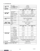
Page 11: ... is ready for operation upon installation Someunits aredual voltageunits designed to operateon 190 230 or 380 460 volts AC 3 phase 50 60 hertz power refer to section 2 4 Other units are designed to operate on 380 460 volts AC 3 phase 50 60 hertz power only An external autotransformer is required for 190 230 vac operation refer to Figure 2 7 and section 2 4 Operating control power is provided by a ...

Page 12: ...ow Suction D Pressure O Dehumid Trans Communi Interface Temperature Power Fa Corrector Arctic O Hermet Composite g 69NT40 511 201 NT0448 P X X X P X X X 77 01698 38 69NT40 511 201 NT0569 P X X X P X X X X 77 01698 60 69NT40 511 201 NT0602 P X X X P X X X X X 77 01698 60 A Factory Installed Pressure Gauges B Factory Installed Pressure Transducers P Provision X Features that apply to model Features ...

Page 13: ...ows access to the evaporator coil heaters The unit model number serial number and parts identification number will be found on the front of the unit to the left of the compressor 1 2 3 4 5 6 7 1 Access Panel For Evap Fan Motor 1 2 Access Panel For Heater 3 Fork Lift Pockets 4 Unit Serial Number Model Number and Parts Identification Number PID Plate 5 Interrogator Connector IC 6 Lower Fresh Air Mak...

Page 14: ...d and discharging the air through the bottom of the refrigeration unit into the container When transporting perishable chilled commodities the fan motors will normally be in high speed above 10_C 14_F or 5_C 23_F optionally The evaporator coil heaters are accessible by removing the front lower access panel The defrost termination sensor is located on the coil center tube sheet and may be serviced ...

Page 15: ...efrost Termination Sensor DTS 8 Heat Termination Thermostat HTT 9 Evaporator Coil 10 Evaporator Coil Heaters 11 Hermetic Thermostatic Expansion Valve 12 Drain Pan Heater DPH 13 Heat Exchanger 14 Interrogator Receptacle IC Optional 15 USDA Probe Receptacle PR2 Optional 16 USDA Probe Receptacle PR1 Optional 17 USDA Probe Receptacle PR3 Optional 18 Cargo Probe Receptacle PR4 Optional Figure 2 2 Evapo...

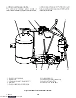
Page 16: ...are located at the right side of the compressor and the suction line process tube 1 2 3 4 5 6 7 11 10 14 9 13 15 12 16 8 1 Power Autotransformer TRANS 2 Power Cables and Plug 3 Compressor Sight Glass View Port 4 Compressor Guard 5 Supply Temperature Sensor STS 6 Ambient Sensor AMBS 7 Discharge Pressure Regulator Valve 8 Suction Line Process Tube 9 Quench Expansion Valve 10 Stepper Motor Suction Mo...

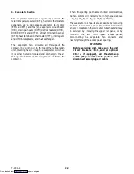
Page 17: ...is pulled in the bottom of thecoil and discharged horizontally out through the front of the condenser fan grille 1 2 3 4 5 6 7 8 2 1 Grille and Venturi Assembly 2 Retaining Screw 3 Condenser Fan 4 Key 5 Condenser Fan Motor CM 6 Condenser Coil Cover 7 Condenser Coil 8 Condenser Motor Mounting Bracket Figure 2 4 Condenser Section Downloaded from ManualsNet com search engine ...
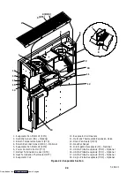
Page 18: ...ouplings waterpressureswitch WP and the liquid line process tube 7 8 1 2 3 4 6 9 5 1 Water Cooled Condenser 2 Rupture Disc 3 Condenser Pressure Transducer CPT 4 Filter Drier 5 Moisture Liquid Indicator Sight Glass 6 Coupling Water In 7 Self Draining Coupling Water Out 8 Liquid Line Process Tube 9 Water Pressure Switch WP Figure 2 5 Water Cooled Condenser Section Downloaded from ManualsNet com sear...

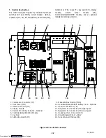
Page 19: ...3 4 5 6 7 8 9 1 Compressor Contactor CH 2 Hour Meter HM 3 Heater Contactor HR 4 Display Module 5 Remote Monitoring Unit CI Optional 6 Controller DataCORDER Module 7 Key Pad 8 Start Stop Switch ST 9 Manual Defrost Switch MDS 10 Controller DataCORDER Battery Pack Optional 11 Control Transformer TR 12 Evaporator Fan Contactor EF High Speed 13 Evaporator Fan Contactor ES Low Speed 14 Condenser Fan Con...

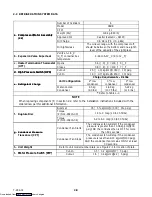
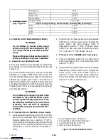
Page 20: ...t Charge Water Cooled Condenser 4 5 kg 9 0 lbs 4 88 kg 10 75 lbs 5 22 kg 11 5 lbs Refer to Table 1 1 NOTE When replacing components f in section 2 2 refer to the installation instructions included with the ordered new part for additional information Bursts at 35 5 kg cm 500 5 psig f Rupture Disc Torque P N 14 00215 03 1 4 to 2 mkg 10 to 15 ft lbs f Rupture Disc Torque P N 14 00215 04 6 2 to 6 9 mk...

Page 21: ...ers 4 e Evaporator Coil Rating 750 watts 5 10 each 230 vac e Evaporator Coil Heaters DHBL Resistance cold 66 8 to 77 2 ohms Heaters DHBL DHBR DHTL DHTR Ambient 20 _C 68_F Type Sheath 380 vac Single Phase 50 hz 460 vac Single Phase 60 hz Full Load Amps High Speed 1 6 amps 2 0 amps Full Load Amps Low Speed 0 8 amps 1 0 amps Nominal Horsepower High Speed 0 70 hp 0 84 hp f Evaporator Fan Nominal Horse...

Page 22: ...he start stop switch ST the unit circuit breaker s CB 1 and CB 2 if equipped and any external power source to their OFF positions b To Operate Unit on 190 230 vac Power Supply 1 Make sure that the start stop switch ST on control panel and circuit breaker CB 2 if equipped on the modular transformer are in position 0 OFF Make sure the 460 vac power plug is locked into the receptacle on the modular t...

Page 23: ... a Connect the water supply line to the inlet side of condenserand thedischargelineto theoutlet sideof the condenser b Maintain a flow rate of 11 to 26 liters per minute 3 to 7 gallons per minute The water pressure switch will open to de energize the condenser fan relay unless overridden by the out of range lockout feature if so equipped The condenser fan motor will stop and will remain stopped un...

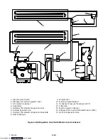
Page 24: ...6 External Equalizer Line 7 Hermetic Thermostatic Expansion Valve Bulb 8 Heat Exchanger 9 Rupture Disc 10 Moisture Liquid Indicator 11 Condenser Pressure Transducer CPT 12 Filter Drier 13 Water Cooled Condenser 14 Stepper Motor Suction Modulation Valve SMV 15 Quench Expansion Valve Figure 2 8 Refrigeration Circuit with Water Cooled Condenser Downloaded from ManualsNet com search engine ...

Page 25: ...he disc with the percentage of desired air flow marked on the supplied label see Figure 2 1 2 8 LOWER FRESH AIR MAKEUP VENT Optional The purpose of the lower fresh air makeup vent is to provide ventilation for commodities that require fresh air circulation The vent must be closed when transporting frozen foods Air exchange depends on static pressure differential which will vary depending on the co...

Page 26: ... will shut down if one of the following safety devices open a Circuit Breaker s b Fuse F3 10A or c EvaporatorFan MotorInternal Protector s IP EM Table 2 1 Safety and Protective Devices UNSAFE CONDITION SAFETY DEVICE DEVICE SETTING Circuit Breaker CB 1 Manual Reset Trips at 29 amps 460 vac Excessive current draw Circuit Breaker CB 2 50 amp Manual Reset Trips at 62 5 amps 230 vac Circuit Breaker CB ...

Page 27: ...n control electric heat control and defrost to ensure continuous conditioned air delivery to the load b Provide dual independent readouts of set point and supply or return air temperatures c Provide digital readout and ability to select data Refer to Table 3 3 for Controller Function Codes For Controller alarm digital display identification refer to Table 3 4 d Provide a pre trip step by step chec...

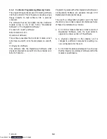
Page 28: ...al Software what physical components are built into the container unit Refer to Table 3 1 Programming cards with eitherOperational Softwareor Configuration Software are available through CTD Replacement Components Group The use of a configuration program card in the field should only occur under unusual circumstances Some of these circumstances may include a A Controller module that has an older v...

Page 29: ...s OFF No 17 Discharge Pressure Sensor Out No In Yes 18 Heater Old Low Watt nEW High Watt 19 Controlled Atmosphere Out No In Yes 20 Pressure Sensor Suction Out No In Yes 21 Auto Transformer Std 22 Economy Mode Option OFF Std Full 23 Defrost Interval Timer Save Option nOSAv SAv 24 Advanced Pre Trip Enhanced Test OFF On 25 Pre Trip Test Points Results Recording rSLtS dAtA 26 Heat Lockout Set to 10_C ...

Page 30: ...wnward Scan alarm list downward Change user selectable features downward Pre trip repeat backward DataCORDER Function and Alarm Codes are scrolled downward after the ALT MODE key is depressed Return Supply Displays non controlling probe temperature momentary display _C _F Displays alternate temperature scale momentary display Alarm List Displays alarm list and clearing of the alarm queue when foll...

Page 31: ... the perishable ranges and the return air probe is used for control in the frozen ranges S Alarm Red LED Energized when there is an active or an inactive shutdown alarm AL20 to AL27 in the alarm queue S Supply Yellow LED Energized when supply temperature and set point are displayed Flashes if dehumidification or humidification is enabled on units so equipped S Return Yellow LED Energized when retu...

Page 32: ...processing the current draws are used to determine control unit operations Whenever a heater or a motor is turned ON or OFF the current draw increase reduction for that activity is measured The current draw is then tested to determine if it falls within the expected range of values for the unit Failure of this test will result in a pre trip failure or a control alarm indication Cd07 Main Power Vol...

Page 33: ...lkaline batteries with voltages greater than 7 5 volts FAIL will be displayed for battery voltages between 4 5 and 7 0 volts and will be displayed for battery voltages less than 4 5 volts After the result is displayed for four seconds btest will again be displayed and the user may continue to scroll through the various codes Cd20 Config Model This code indicates the dash number of the model for wh...

Page 34: ... delaying a needed defrost cycle NOTE The defrost interval timer counts only during compressor run time Cd28 Temperature Units _C or _F This code determines the temperature units _C or _F which will be used for all temperature displays The user selects _C or _F by selecting function code Cd28 and pushing the ENTER key The factory default value is Celsius units NOTE This function code will display ...

Page 35: ...Cd33 the user may then change code Cd35 to bulb After bulb has been selected and entered the user may then utilize function codes Cd36 and Cd37 to make the desired changes Cd36 Evaporator Speed Select Cd35 must be in Bulb This code is enabled only if a dehumidification set point has been selected using function code Cd33 and bulb has been selected using function code Cd35 If these conditions are n...

Page 36: ...problem is found to exist its alarm code will be alternately displayed with the set point on the left display S The user should scroll through the alarm list to determine what alarms exist or have existed Alarms must be diagnosed and corrected before the Alarm List can be cleared To Display Alarm Codes While in Set Point Selection or Default Display mode press the ALARM LIST key This accesses the ...

Page 37: ...er determines that all of the control sensors are out of range This can occur for box temperatures outside the range of 50_C to 70_C 58_F to 158_F This alarm triggers the failure action code set by Function Code Cd29 AL27 Probe Circuit Calibration Failure The Controller has a built in Analog to Digital A D converter used to convert analog readings i e temperature sensors current sensors etc to dig...

Page 38: ...on Thermostat HTT Safety Alarm 59 is triggered by the opening of the heat termination thermostat HTT and will result in the disabling of the heater This alarm will remain active until the thermostat resets AL60 Defrost Termination Sensor Failure DTS Alarm 60 is an indication of a probable failure of the defrost termination sensor DTS It is triggered by the opening of the heat termination thermosta...

Page 39: ...erature Sensor Failure CPSS Alarm 69 is triggered by a suction temperature sensor reading outside the valid range of 60_C 76_F to 150_C 302_F This is a display alarm and has no associated failure action NOTE If the Controller is configured for four probes without a DataCORDER the DataCORDER alarms AL70 and AL71 See Table 3 7 will be processed as Controller alarms AL70 and AL71 The Controller perfo...

Page 40: ...10_C 14_F or 5_C 23_F optionally See Figure 3 5 and Figure 3 6 The Controller configuration variable for Heat Lockout refer to Table 3 1 can be changed for set points of either 10_C 14_F or 5_C 23_F optionally NOTES S When upward set point changes aremadeat ambients below 27_C 80_F the compressor is immediately cycled OFF The compressor three minute time delay will be overridden so that as soon as...

Page 41: ...itions are satisfied the Controller will activate the heat relay to begin dehumidification 1 The humidity sensor reading is above the set point and valid AL67 2 The pulldown mode is NOT active ie The control temperature is less than 5_C above set point 3 The control probe i e Supply 1 temperature is less than set point plus 0 25_C 4 Temperature control set point is greater than 10_C 14_F or 5_C 23...

Page 42: ...o low speed any time the supply air temperature is within 0 25_C 0 45_F of the set point and the return air temperatureis less than or equal to the supply air temperature 3_C 5 4_F When the fans switch to low speed they will run in low speed for one hour At the end of the hour the evaporator fans will switch back to high speed The evaporator fans will again run in high speed for three minutes and ...

Page 43: ...ow that it is enabled so a manual display of function code Cd34 must be performed to enable the user to see its current status A second way to deactivate economy mode is to change the set point Once economy mode is deactivated the system will return to normal control mode operations In order to achieve economy mode frozen operation a frozen set point temperature must be selected PRIOR to activatin...

Page 44: ...nce power up then theright display will show Auto or Auto 1 The user may scroll through the test selection menu using the arrow keys A given test is selected by pressing ENTER while it is displayed The entire battery of tests may be run by pressing ENTER while Auto 1 or Auto 2 is displayed During this selection mode failure to press either an arrow key or ENTER for five seconds will return the uni...

Page 45: ...cludes the following P P1 P2 P3 P4 P5 P6 P7 P8 P9 P10 and rSLts Refer to section 3 2 1 P Pre Trip Initiated All lights and display segments will be energized for five seconds at the start of the pre trip Since the unit cannot recognize lights and display failures there are no test codes or results associated with this phase of pre trip P1 0 Heaters Turned On Setup Heater must start in the OFF cond...

Page 46: ... the return and supply probes NOTE If this test fails P5 0 and FAIL will be displayed If both Probe tests this test and the PRIMARY SECONDARY pass the display will read P5 PASS P5 1 Supply Probe Test Requirements For units equipped with secondary supply probe only Pass Fail Criteria The temperature difference between primary and secondary probe supply is compared NOTE If this test fails P5 1 and F...

Page 47: ...r pressure transducer CPT or discharge pressure if equipped with either a discharge pressure transducer DPT or a condenser pressure transducer CPT Pass Fail Criteria The test fails if high pressure switch fails to open in 900 seconds Note this test is skipped if the unit does NOT have S A compressor discharge sensor CPDS S A discharge pressure transducer DPT S Condenser pressure transducer CPT P7 ...

Page 48: ...age recorder supply temperature will be recorded in the DataCORDER as well as stored in memory for use in applying the test pass fail criteria Pass Fail Criteria If the recorded temperature is within 0 5_C of set point from test start to DataCORDER recording the test passes If the average temperature is outside of the tolerance range at the DataCORDER recording the test fails P9 0 Defrost Test Set...

Page 49: ... start to DataCORDER recording the test passes If temperature is outside of the tolerance range at the DataCORDER recording the test fails 3 3 INTEGRATED DATACORDER Optional 3 3 1 Brief Description Carrier Transicold has developed a recorder which we have termed the DataCORDER and is integrated into a module with the Controller For reader simplicity and understanding this section has been separate...

Page 50: ...ion cards are available thru CTD Replacement Components Group The use of a programming card in the field should only occur under unusual circumstances such as a physical component in thecontainer unit is changed to adifferent component resulting in a new configuration for the unit ITEM SETTING FACTORY DEFAULT Sensor Logging Network Average or Snapshot Average Sensor Logging Thermistor Average Snap...

Page 51: ...N Left 4 Right 4 The DataCORDER serial number consists of eight characters Function code dC26 contains the first four characters Function code dC27 contains the last four characters This serial number is the same as the Controller serial number dC28 Minimum Days Left An approximation of the number of logging days remaining until the DataCORDER starts to overwrite the existing data dC29 Days Stored...

Page 52: ...CORDER Alarm Indications S IAXX if the alarm is inactive END is displayed to indicate the end of the alarm list if any alarms are active CLEAr is displayed if all the alarms in the list are inactive S The exception to this rule is the DataCORDER Alarm Queue Full AL91 alarm which does not have to be inactive in order to clear the alarm list To Clear the Alarm List If no alarms are active the Alarm ...

Page 53: ... range See NOTE below NOTE While the DataCORDER is normally setup to record only supply and return recorder sensors the DataCORDER has the capability to record the data of eight additional sensors Any sensor installed on the unit may be recorded and are identifiable as Network Sensors AL 78 to AL85 Which alarm AL78 to AL 85 is associated with the physical sensor depends on how the DataCORDER was c...

Page 54: ...es configuration and scrollback b DataCORDER Power Up TheDataCORDER may bepowered up in several ways 1 Normal AC power The DataCORDER is powered up when the unit is turned on via the stop start switch ST 2 Normal DC power If a rechargeable battery pack is installed fully charged the user may plug the interrogation cable into the front interrogation receptacle and the DataCORDER will power up for c...

Page 55: ...cer CPT Standard Mode The standard recording mode allows the user to configure the DataCORDER to monitor data using one of seven standard configurations The seven standard configuration variables with their descriptions are listed in Table 3 9 The six thermistor inputs supply return USDA 1 2 3 and cargo probe and the humidity sensor will be DataCorder inputs The three inputs will be read over a ne...

Page 56: ... label on the back panel of the unit shows which receptacle is used for each probe The USDA 1 2 and 3 probes and possibly the optional Cargo probe are installed in their receptacles The DataCORDER records up to six probe temperatures supply return USDA 1 2 3 and an optional cargo probe 4 at the logging interval The standard DataCORDER report displays the supply and return air temperatures The cold...

Page 57: ...e within the DataCORDER memory thus meeting USDA criteria refer to section 3 3 7 The following is a summary of the steps required to initiate a USDA Cold Treatment a Pre cool the container to the treatment temperature or below b Pre cool to treatment temperature c Install the DataCORDER module battery pack if not already installed d Calibrate the three USDA probes by ice bathing the probes and per...

Page 58: ...kip Result Change in currents for Phase A B and C 6 1 Not Applicable This test is not in use starting with model number 69NT40 511 200 and UP 6 2 Suction Modulation Valve Open and Closed Pass Fail Skip Result Is current or pressure limit in effect Y N 6 4 Not Applicable This test is not in use starting with model number 69NT40 511 200 and UP 6 5 Not Applicable This test is not in use starting with...

Page 59: ... No Alarms Reported USDA SUMMARY LEGEND DATE 15Apr94 23 49 Trip Start SP Setpoint Change PS PE Pretrip Start End NEW SN Controller Rep dal Datacorder Alm NEW SW Software Upgrade DS Defrost Start DHS DHE Dehumid Start End NEW ID Container ID OFF Power Loss COMM NetWork Off DE Defrost End AL Alarm Activity TS Trip Start BATT Power Loss Setp SupAir RetAir Figure 3 4 Standard Configuration Report Samp...

Page 60: ..._C 14_ _ _ _F or 5_ _ _ _C 23_ _ _ _F optionally SET POINT FALLING TEMPERATURE RISING TEMPERATURE 1 5_ _ _ _C 2 7_ _ _ _F 1_ _ _ _C 1 8_ _ _ _F 0 5_ _ _ _C 0 9_ _ _ _F 0 20_ _ _ _C 20_ _ _ _C 1 5_ _ _ _C 2 7_ _ _ _F 1_ _ _ _C 1 8_ _ _ _F 0 5_ _ _ _C 0 9_ _ _ _F HEATING HEATING MODULATING COOLING AIR CIRCULATION ONLY AIR CIRCULATION and possible modulated cooling MODULATING COOLING NOTE For In rang...

Page 61: ...rical connections or hardware e Check color of moisture liquid indicator f Check oil level in compressor sight glass g Start refrigeration unit Refer to section 4 3 4 2 STARTING AND STOPPING INSTRUCTIONS CAUTION Make sure that the unit circuit breaker s CB 1 CB 2 and the start stop switch ST are in the OFF position before connecting to any electrical power source a Starting the Unit NOTE The evapo...

Page 62: ...diagnostic check that does not fall outside of the limits as described under standard or special as outlined above If AL55 is active meaning that the DataCORDER DC functionality is no longer active DC configuration variable off the Controller will act as a four probe configured system during probe checks The only differences will be that the Controller Function Codes Cd38 and Cd39 will become enab...

Page 63: ...4 3 T 294 01 Page is left intentionally blank Downloaded from ManualsNet com search engine ...

Page 64: ...nergized Also at this time the cool light is illuminated When the air temperature decreases to a predetermined tolerance above set point relay TI energizes and the in range light is illuminated Refer to section 3 1 4 Code 30 If the air temperature continues to fall modulating cooling starts at approximately 2 5_C 4 5_F above set point During this cooling mode a running sum of the temperature diffe...

Page 65: ...4 5 T 294 01 18 Volt Energized Circuit CONTROL TRANSFORMER 24 Volt Energized Circuit De energized Circuit Figure 4 1 Cooling Mode Downloaded from ManualsNet com search engine ...

Page 66: ...or fans continue to run to circulate air throughout the container As the supply air decreases to the in range tolerance below set point relay TI and the in range light de energize after a 15 minute time delay and will remain de energized until the supply air increases to a tolerance below set point Refer to section 3 1 4 Code 30 When the temperature rises to 0 2_C 0 4_F below set point TH opens he...

Page 67: ...4 7 T 294 01 18 Volt Energized Circuit CONTROL TRANSFORMER 24 Volt Energized Circuit De energized Circuit Figure 4 2 Heating Mode Downloaded from ManualsNet com search engine ...

Page 68: ...ay also be forced to terminate through special communication commands Upon completion of the de ice phase of defrost the controller will perform a probe check cycle The purposeoftheprobecheck cycleis to perform aperiodic check of the controller sensors to detect malfunctions or drift in the sensed temperature that is too small to be detected by the normal sensor out of range tests The system will ...

Page 69: ...me period Pre Trip will be allowed to run normally OncePre Trip is over the controller will revert to its normal control mode logic If ambient is warmer than 10 0_C the system will run its normal startup logic Arctic mode is configurable by using the configuration variable 29 refer to Table 3 1 CONTROL TRANSFORMER 18 Volt Energized Circuit 24 Volt Energized Circuit De energized Circuit Figure 4 3 ...

Page 70: ...efer to section 3 1 7 a 2 De energized Heater Contactor HR De energized De energized Energized INDICATING LIGHTS Cool ON OFF OFF Defrost OFF OFF ON In Range On If In Range Refer to paragraph 3 1 4 Code 30 Heat OFF OFF ON POWER CIRCUIT Compressor Energized De energized De energized Condenser Fan Motor Energized De energized De energized Heaters De energized De energized Energized Evaporator Fan Mot...

Page 71: ...d De energized Energized Energized Energized INDICATING LIGHTS Cool ON OFF ON OFF OFF Defrost OFF OFF OFF OFF ON In Range On If In Range Refer to paragraph 3 1 4 Code 30 Heat OFF OFF ON ON ON POWER CIRCUIT Compressor Energized De energized Energized De energized De energized Condenser Fan Motor Energized De energized Energized De energized De energized Heaters De energized De energized Energized E...

Page 72: ...heck Compressor hums but does not start Shorted or grounded motor windings 6 8 Compressor seized 6 8 5 2 UNIT RUNS BUT HAS INSUFFICIENT COOLING Compressor Compressor valves defective 6 8 Abnormal pressures 5 7 Temperature controller malfunction 5 9 Refrigeration System Evaporator fan or motor EM defective 6 16 Refrigeration System Stepper motor suction modulation valve SMV malfunction 6 24 Condens...

Page 73: ...nal connections Tighten Low line voltage 2 4 5 5 UNIT WILL NOT TERMINATE HEATING Temperature controller improperly set Reset Unit fails to stop heating Temperature controller malfunction 5 9 Unit fails to stop heating Heater termination thermostat HTT remains closed along with the heat relay TH 6 14 5 6 UNIT WILL NOT DEFROST PROPERLY Defrost timer malfunction 3 1 4 Loose terminal connections Tight...

Page 74: ...Replace Suction and discharge pressures tend to equalize when unit is Compressor valves defective 6 9 q operating Compressor cycling stopped Check 5 8 ABNORMAL NOISE OR VIBRATIONS Loose mounting bolts Tighten Compressor Worn bearings 6 8 Compressor Worn or broken valves 6 8 Liquid slugging 5 11 Bent loose or striking venturi Check Condenser or Evaporator Fan Worn motor bearings 6 16 6 19 Condenser...

Page 75: ...valve 6 5 6 6 Liquid slugging in compressor Pin and seat of expansion valve eroded or held open by foreign material 6 25 Fluctuating suction pressure Improper bulb location or installation 6 25 Fluctuating suction pressure Low superheat setting 6 25 5 12 POWER AUTOTRANSFORMER MALFUNCTION Circuit breaker CB 1 or CB 2 tripped Check Unit will not start Power transformer TRANS defective 6 21 Unit will...

Page 76: ...ht and round 2 Carefully clean the process tubing where the piercing valve will be attached do NOT scratch the tubing 3 Make sure there are no dents in the tubing 4 Apply a little clean refrigerant oil to the tubing where the piercing valve will be placed b Installing 1 Make sure the gasket item 2 refer to Figure 6 1 is in place and the piercing needle item 3 is backed all the way out by turning t...

Page 77: ...all the way out high pressure vapor will flow into thelow side When thelow pressurevalve is open the system can be charged Oil can also be added to the system Only a R 134a manifold gauge set with self sealing hoses as shown in Figure 6 3 CTD P N 07 00294 00 which includes items 1 through 6 can be used when working on the models covered within this manual Opened Backseated Hand Valve Closed Fronts...

Page 78: ...ue Knob 1 Manifold Gauge Set 2 Hose Fitting 0 500 16 Acme 3 Refrigeration or Evacuation Hoses SAE J2196 R 134a 4 Hose Fitting w O ring M14 x 1 5 5 High Side Field Service Coupling 6 Low Side Field Service Coupling Figure 6 3 R 134a Manifold Gauge Set Connection Downloaded from ManualsNet com search engine ...

Page 79: ...and suction line process tubes S Using the tubing cutter cut the process tubes below the pierced hole in liquid line and suction line process tubes S Place the 3 8 inch flare nuts on both process tubes and flare the tube S Connect the 3 8 inch to 1 4 inch flare adapter and the 1 4 inch swivel elbow x R 134a refrigerant adapter to the R 134a gauge set The refrigeration unit is now ready for repair ...

Page 80: ...6 5 T 294 01 2 1 1 Liquid Line Process Tube 2 Suction Line Process Tube Figure 6 4 Refrigerant Recovery Process Tubes Downloaded from ManualsNet com search engine ...

Page 81: ...an 15 6_C 60_F ice might form before moisture removal is complete Heat lamps or alternate sources of heat may be used to raise the system temperature e To help speed up the evacuation procedure replace the filter drier with a section of 3 8 inch ID copper tubing 6 6 3 Procedure a Remove all refrigerant using a refrigerant recovery system b The recommended method to evacuate and dehydrate the syste...

Page 82: ...ight of refrigerant has been added as indicated by scales Correct charge is noted in Table 6 9 NOTE It may be necessary to finish charging the unit through the suction line process tube in gas form due to pressure rise in high side of the system Refer to section 6 7 3 d Backseat the manifold gauge port Close liquid valve on cylinder e Start unit in cooling mode Run approximately 10 minutes and che...

Page 83: ...ed operation if necessary i Leave piercing valves in place for Port repair j Tag the unit for Port Maintenance repair 9 8 7 6 5 4 4 4 3 2 1 10 11 1 Refrigerant Recovery Unit 2 Refrigerant Cylinder 3 Evacuation Manifold R 134a 4 Hand Valve 5 Vacuum Pump 6 Electronic Vacuum Gauge 7 Condenser Coil 8 Compressor 9 Evaporator Coil 10 Liquid Line Process Tube 11 Suction Line Process Tube Figure 6 5 Vacuu...

Page 84: ...fer to section 2 2 for weight of compressor g Remove high pressure switch HPS from compressor and check operation of switch refer to section 6 13 2 h Remove compressor mounting bolts from mounting plate and install mounting plate on replacement compressor 1 2 3 4 5 6 7 8 10 11 12 13 14 15 9 1 Discharge Flange 2 High Side Pressure Connection 3 Low Side Pressure Connection 4 Suction Flange 5 Motor E...

Page 85: ...me units have a plug in the bottom center of the crankcase which may be removed for draining the motor end more quickly b Remove cylinder head capscrews If the cylinder head is stuck tap the center of the cylinder head with a wooden or lead mallet DO NOT STRIKE THE SIDE OF THE CYLINDER HEAD Be careful not to drop the head or damage the gasket sealing surface See Figure 6 6 and Figure 6 7 Remove cy...

Page 86: ...r end cover as the cover fits over the winding coils Remove all capscrews except one in the top of the cover Then while holding the cover in place remove the remaining capscrew Do not allow the cover to drop from its own weight To prevent striking the winding remove the cover horizontally and in line with the motor axis h Remove the refrigerant suction strainer If it is removed with ease it may be...

Page 87: ...e terminal mounting plate assembly as originally installed is assembled so as to leave a small space between the outer terminal bushing and the surface of the mounting plate This is to provide further crush of theterminal bushing in casealeak should occur To stop a leak tighten the terminal bushing nut only enough to stop the escape of gas Do not tighten until the terminal bushing is flush with th...

Page 88: ... 6 16 Piston Rings c Installing the Components 1 Push pistons from the inside of the crankcase through the cylinders being careful not to break the rings Place chamfered side of connecting rod against radius of crankpins Install the crankshaft through the pump end of the compressor Do not damagemain bearings Install matching connecting rod caps through bottom cover plate 2 The oil screen located i...

Page 89: ...nifold common connection remains immersed in oil at all times Otherwise air and moisture will be drawn into the compressor Connect the suction connection of the gauge manifold to the compressor liquid line process tube refer to sections 6 3 and 6 4 and immerse the common connection of the gauge manifold in an open container of refrigeration oil Crack the manifold gauge valve to vent a small amount...

Page 90: ...isture liquid indicator shows moisture in the system b To Replace Filter Drier WARNING Residual system oil can cause a fire and potential injury To avoid the possibility of an oil fire when replacing the filter drier use the following procedure Oil Fire extinguishing source is REQUIRED to be at your disposal during the repair NOTE Run unit in a FULL COOL operation for 20 minutes before beginning P...

Page 91: ... dry nitrogen See Figure 6 19 d Set nitrogen pressure regulator at 26 4 kg cm 375 psig with bleed off valve closed e Close valve on cylinder and open bleed off valve f Open cylinder valve Slowly close bleed off valve to increase pressure on switch The switch should open at a static pressure up to 25 kg cm 350 psig If a light is used light will go out If an ohmmeter is used the meter will indicate ...

Page 92: ...oil where it is either heated or cooled and then discharged out the bottom of the refrigeration unit into the container Refer to section 2 3 The fan motor bearings are factory lubricated and do not require additional grease a Replacing the Evaporator Fan Assembly WARNING Always turn OFF the unit circuit breakers CB 1 CB 2 and disconnect main power supply before working on moving parts 1 Remove upp...

Page 93: ...used in the high speed circuit and another capacitor used for the low speed circuit a When to check for a defective capacitor 1 Fan motor will not change speed For example controller settings above 10_C 14_F or 5_C 23_F optionally should cause the motor to run in high speed NOTE The evaporator fan motors will always start in high speed Controller settings below 10_C 14_F or 5_C 23_F optionally sho...

Page 94: ...rge line and remove the line to the receiver or water cooled condenser if so equipped 4 Remove coil mounting hardware and remove the coil 5 Install replacement coil and solder connections 6 Leak check the coil per section 6 5 Evacuate the unit per section 6 6 then charge the unit with refrigerant per section 6 7 1 6 19 CONDENSER FAN AND MOTOR ASSEMBLY WARNING Do not open condenser fan grille befor...

Page 95: ...es not appear to be functioning check the following a Make sure power to the unit is OFF b Refer to Figure 2 7 for the location of TBU c Disconnect the TBU from across the autotransformer This will isolate the device and allow for accurate measurements d Using a capacitor meter i e Fluke 87 measure between L1 and L1 L2 and L2 L3 and L3 e Thereadings should be0 44 µF plus or minus 14 f If the readi...

Page 96: ...y for reuse on the replacement probe Do not cut the grommet d Cut one wire of existing cable 41 mm 1 5 8 inches shorter than the other wire e Cut one replacement sensor wire opposite color back 41 mm 1 5 8 inches See Figure 6 22 Sensor 41 mm 1 5 8 inches 6 35 mm 1 4 inch Figure 6 22 Sensor RRS RTS SRS or STS f Strip back insulation on all wiring 6 35 mm 1 4 inch g Slide a large piece of heat shrin...

Page 97: ...propane torch will work caution should betaken not to burn theheat shrinktubingor wire insulation Make sure all seams are sealed tightly against the wiring to prevent moisture seepage k Slide large heat shrink tubing over both splices and shrink tubing and heat as in step j CAUTION Do not allow moisture to enter wire splice area as this may affect the sensor resistance l Check sensor resistance as...

Page 98: ...per function of the sensor 6 24 STEPPER MOTOR SUCTION MODULATION VALVE SMV On start up of the unit the valve will reset to a known open position This is accomplished by assuming the valve was fully open driving it fully closed resetting the percentage open to zero then opening to a known 21 staging position This makes the unit ready to start and normal operation will begin 2 1 8 inch Nut 2 1 1 Ste...

Page 99: ...his Dependent on ambient conditions there should be an increase in suction pressure and current draw as the valve opens however this may be difficult at times to fully determine 5 If the unit still does not operate properly stop unit and check out the SMV system refer to section 6 24 b b Checking the Stepper valve Disconnect the four pin connector to the stepper SMV With a reliable digital ohmmete...

Page 100: ... only be checked with the connector assembled as this is an open collector type circuit By checking the outputs on A B and E it can be verified that the controller is attempting to communicate with the drive module To be thorough and if it is desired the TTL signals on pins C and D can be checked as follows S Make up a jumper assembly in which the drive module and controller connectors can be join...

Page 101: ...ure determined in step 6 from the average temperature measured in step 5 The difference is the superheat of the suction gas b Removing the Expansion Valve NOTES S The hermetic TXV does NOT have adjustable superheat S All connections on the hermetic TXV are bi metallic copper on the inside and stainless on the outside S All joints on the hermetic TXV inlet outlet and equalizer lines are brazed S Bi...

Page 102: ...inlet connection to inlet line seeFigure 6 31 5 Braze outlet connection to outlet line 6 Reinstall the cushion clamps on inlet and outlet lines 7 Braze the equalizer connection to the equalizerline 8 Check superheat refer to section 2 2 and Table 6 9 Container box temperature should be at 18_C 0_ Copper Tube Apply heat for 10 15 seconds Bi metallic Tube Connection Apply heat for 2 5 seconds Do not...

Page 103: ... and observe the meter needle If the capacitor is good the needle will make a rapid swing toward zero resistance and then gradually swing back toward a very high resistance reading The reading should read about 330 000 ohms for a good capacitor due to the discharge resistors If the capacitor has failed open the ohmmeter needle will not move when the meter probes touch the terminals If the capacito...

Page 104: ...protect the Controller DataCORDER module from both physical and electrostatic discharge damage during storage and transit Installation Install the module by reversing the steps in section 6 27 b Torque values for mounting screws item 1 Figure 6 32 are 0 23 mkg 20 inch pounds and 0 12 mkg 10 inch pounds for all connectors MA MB MC KA KB 1 2 3 4 1 Controller DataCORDER Software Programming Port 2 Mo...

Page 105: ...h OFF and remove the card 5 Press the ENTER key on the keypad 6 The Display module will read a When the software loading has successfully completed the Display will show the message EEPrM donE b If a problem occurs while loading the software the Display will blink the message Pro FAIL or bad 12V Turn start stop switch OFF and remove the card 7 Turn unit OFF using start stop switch ST 8 Remove the ...

Page 106: ...e scaling operation by rinsing and neutralizing equipment before putting it back into service Their knowledge of metals types of scale water conditions and de scaling techniques will be highly useful to you Summary of Procedure a Drain water from condenser tubing circuit Clean water tubes with Oakite No 22 to remove mud and slime b Flush c De scale water tubes with Oakite No 32 to remove scale d F...

Page 107: ...to neutralize Drain this solution 10 Flush the tubes thoroughly with fresh water NOTE If the condenser cooling water is not being used as drinking water or is not re circulated in a closed or tower system neutralizing is not necessary 11 Put the unit back in service and operate under normal load Check the head pressure If normal a thorough de scaling has been achieved What You Can Do For Further H...

Page 108: ... threaded brass inserts that are molded into the control box will need to be replaced if the threads become stripped or if the insert becomes loose The inserts and epoxy are contained in repair kit CTD part number 76 50084 00 see Table 6 2 There are 6 different inserts used in the control box Refer to Figure 6 36 for the locations of the various inserts NOTE An epoxy application gun is also needed...

Page 109: ...ads 34 06231 05 10 6 Insert 12 7 x 9 91 mm 5 x 390 in 1 4 20 Threads 34 06231 06 10 7 Insert 9 53 x 6 76 mm 375 x 266 in 10 24 Threads 34 06231 07 10 8 Durabond Epoxy E20 HP Loctite 29314 02 0082 00 1 9 Static Mixing Tube Loctite 983440 07 00390 00 1 10 Instruction Sheet 98 02338 00 1 Note Insert repair procedures require use of an Application Gun Carrier part number07 00391 00 Loctite983435 Table...

Page 110: ...6 35 T 294 01 03 03 03 03 03 04 04 03 01 07 07 05 05 06 INSERT PART NUMBERS 34 06231 WHERE THE IS AS INDICATED Figure 6 36 Insert Location Downloaded from ManualsNet com search engine ...
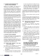
Page 111: ...ntended repair 18 Cleaning materials abrasive cloth tube wire brush stainless steel wool etc 19 Cylinder of R 134a refrigerant 20 Cylinder of dry nitrogen Table 6 5 AMBS DTS RRS RTS SRS and STS Temperature Resistance Chart Temperature Centigrade Temperature Fahrenheit Resistance Ohms RRS RTS SRS and STS 0 32 32 650 91 25 77 10 000 50 AMBS and DTS 0 32 32 650 1720 1620 25 77 10 000 450 430 Table 6 ...

Page 112: ...in Bearing Journal Diameter 1 3735 34 8869 0020 0 0508 CONNECTING ROD 1 3768 34 9707 0020 0 0508 Piston Pin Bearing 0 6878 17 4701 0010 0 0254 CRANKPIN DIAMETER 1 3735 34 8869 0025 0 0635 Throw 1 072 27 2288 1 070 27 1780 THRUST WASHER Thickness 0 154 3 9116 0 1520 03 8608 0250 0 6350 CYLINDERS Bore 2 0010 50 8254 0020 0 0508 Piston Diameter 1 9860 50 4444 0020 0 0508 Piston Pin Diameter 0 6873 17...

Page 113: ...1 38 Oil Pump Drive Segment 12 16 1 66 2 21 Unloader Valve Cover Plate Plate End 16 20 2 21 2 77 Bearing Head 5 16 18 16 20 2 21 2 77 Terminal Block Cap Screws 5 16 18 20 30 2 77 4 15 Suction Flange 20 30 2 77 4 15 Discharge Flange Pump End Bearing Head 3 8 16 40 50 5 53 6 92 Bottom Plate Crankcase Compressor Foot 3 8 16 40 50 5 53 6 92 Cylinder Head 7 16 14 55 60 7 61 8 30 Motor End Cover Crankca...

Page 114: ... 20 65 18 64 1 4 51 4 42 6 21 3 7 26 26 70 21 71 1 5 00 4 90 4 20 4 6 32 32 75 24 78 7 5 53 5 43 2 19 5 6 39 39 80 27 86 7 6 10 5 98 0 18 6 5 46 45 85 29 95 3 6 70 6 57 2 17 7 6 53 52 90 32 104 3 7 33 7 19 4 16 8 6 60 59 95 35 114 0 8 01 7 86 6 14 9 7 68 67 100 38 124 2 8 73 8 56 8 13 10 8 76 74 105 41 135 0 9 49 9 31 10 12 12 0 84 83 110 43 146 4 10 29 10 09 12 11 13 2 93 91 115 46 158 4 11 14 10...

Page 115: ...nt Air Temperature psig 48 9 43 3 37 8 32 2 26 7 21 1 15 6 Bar 0_ _ _ _F 17 8_ _ _ _C Box 5 5 6 9 8 3 9 7 11 0 12 4 13 8 15 2 16 6 19 3 20 7 22 0 17 9 _ _ _ _F _ _ _ _C 35_ _ _ _F 1 7_ _ _ _C Box Ambient Air Temperature psig _F Bar 97 83 69 55 41 28 14 0 14 28 41 0_ _ _ _F 17 8_ _ _ _C Box 48 9 43 3 37 8 32 2 26 7 21 1 15 6 _ _ _ _C 35_ _ _ _F 1 7_ _ _ _C Box Compressor Suction Pressure Versus Amb...

Page 116: ...o the unit is OFF and power plug disconnected before replacing the compressor WARNING Before disassembly of the compressor make sure to relieve the internal pressure very carefully by slightly loosening the bolts on both service valve flanges blank valve pads then lightly tapping sides of the valve flanges pads with a hammer to break the seal CAUTION Use only Carrier Transicold approved Polyol Est...

Page 117: ...7 2 T 294 01 Figure 7 1 Electrical Schematic See Model Chart Sheet 1 of 2 Downloaded from ManualsNet com search engine ...
Page 118: ...7 3 T 294 01 Figure 7 1 Electrical Wiring Schematic See Model Chart Sheet 1 of 2 Downloaded from ManualsNet com search engine ...
Page 119: ...7 4 T 294 01 Figure 7 2 Electrical Schematic See Model Chart Sheet 1 of 2 Downloaded from ManualsNet com search engine ...
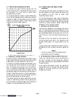
Page 120: ...7 5 T 294 01 Figure 7 2 Electrical Wiring Diagram See Model Chart Sheet 2 of 2 Downloaded from ManualsNet com search engine ...
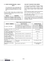
Page 121: ... 6 4 10 4 11 Compressor Crankcase Heater 2 9 4 2 6 9 Compressor Motor 2 4 5 1 6 9 6 29 Compressor Sight Glass 2 4 Condenser Air Cooled 2 12 Coil 5 3 6 18 Specifications 2 9 Water Cooled 2 6 2 12 Condenser Fan Contactor 2 7 4 6 4 8 4 10 4 11 Condenser Fan Motor 2 5 5 3 6 18 6 29 Condenser Fan Relay 4 4 4 8 Condenser Fan Switch 2 11 Condenser Pressure Control 3 3 3 6 3 14 4 4 Condenser Pressure Tran...

Page 122: ...rs 2 3 Evaporator Fan Contactor 2 7 4 4 4 10 4 11 5 2 5 3 Evaporator Fan Motor 2 1 2 3 5 3 6 16 6 29 Specifications 2 9 Exchanger Heat 2 3 2 12 Expansion Valve Superheat 2 8 F Filter Drier 2 6 2 12 5 3 6 15 Flange Discharge 2 4 6 9 6 34 Suction 2 4 6 9 6 12 6 34 Fork Lift Pockets 2 1 Fuses 2 9 2 14 3 1 5 1 5 2 5 3 Specifications 2 9 Fusible Plug 2 14 G Gauge High Pressure 6 2 Low Pressure 6 2 Mani...

Page 123: ...ost 4 8 Frozen Range 3 17 Heating 4 6 Perishable Range 3 14 Moisture Liquid Indicator 2 6 2 12 Motor Compressor 2 4 5 1 6 9 6 29 Condenser Fan 2 5 5 3 6 18 6 29 Evaporator Fan 2 1 2 3 5 3 6 16 6 29 P Pad Key 2 7 Parts Identification Number PID 1 1 1 2 2 1 PID Parts Identification Number 1 1 1 2 2 1 Port Software Programming 3 1 6 28 Power Autotransformer 2 4 2 10 5 1 5 4 6 19 Power Factor Correcto...

Page 124: ... Defrost Termination 2 3 3 7 3 9 3 12 3 16 3 22 5 2 6 16 6 21 Defrost termination 4 8 Discharge Temperature 3 13 3 21 Humidity 2 3 2 10 3 7 3 9 3 13 3 15 Network 3 25 3 27 Positioning Return 6 21 Supply 6 20 Replacing 6 21 Return 6 21 Supply 6 20 Return Recorder 2 3 6 20 Return Temperature 2 3 3 11 3 12 3 25 3 29 4 8 6 19 Suction Temperature 3 13 Supply Recorder 6 20 Supply Temperature 2 4 3 11 3 ...

Page 125: ...nit 2 10 6 19 Troubleshooting 5 1 U Unit Remote Monitoring 2 7 Unit Operation 4 2 Unit Serial Number 2 1 Upper Fresh Air Makeup Vent 2 1 2 13 USDA 3 30 3 31 USDA Probe Receptacle 2 3 V Vacuum Pump 6 6 6 8 Connections 6 8 Valve Discharge Pressure Regulator 2 4 2 12 5 3 Hermetic Thermostatic Expansion 2 3 2 12 5 3 5 4 Quench Expansion 2 4 2 12 3 6 Stepper Motor Suction Modulation 2 4 2 12 3 6 3 15 3...

Reviews: