9
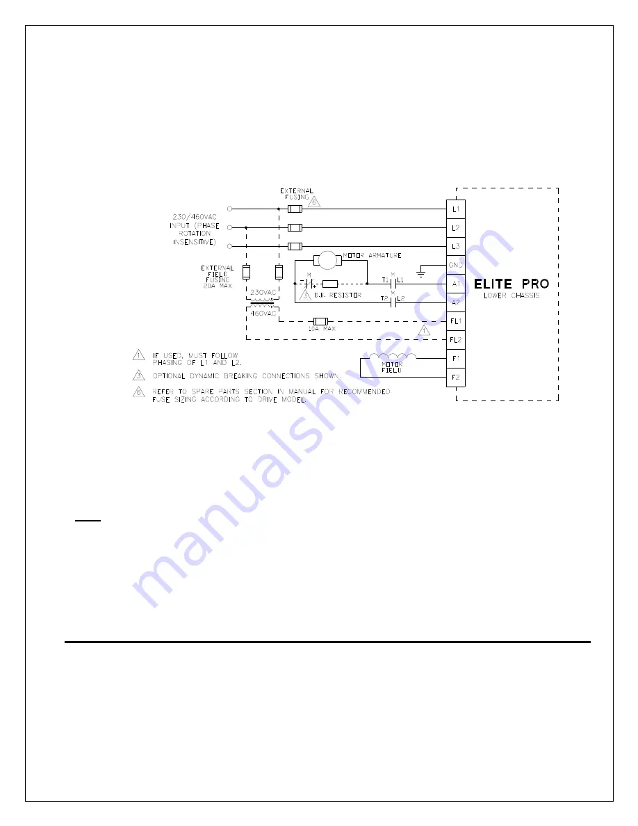
In some cases, the field voltage required by a motor exceeds the maximum obtainable field voltage
that can be derived with the required AC line voltage for the motor armature. In these cases, an
external single phase AC supply for the field bridge must be used. The supply connects to FL1 and
FL2 and must be in phase with the armature supplies L1 and L2. Refer to Figure 3. Jumpers J8 and
J9 on the trigger board need to be moved from internal to external.
For example, if a motor has a 240VDC armature rating, 230VAC lines must be connected to L1, L2,
and L3. The maximum field voltage attainable from the field bridge with 230VAC input is 200VDC. In
order to obtain the required 240VDC field, a single phase 460VAC supply can be connected to FL1
and FL2.
Figure 3
Armature
The armature leads are usually the highest current wires associated with the drive and warrant
special attention to sizing based on current rating as well as length of run. Extra care should be used
where terminations and splices are made. Refer to Table 1 for typical armature voltage, current,
contactor and dynamic braking resistor ratings.
Note
: When present, the
S1
and
S2
for the
SERIES
field winding is placed in series with the
armature leads on the non-regenerative models. It should not be used with the EPR Series
regenerative models and the leads should not be connected and should be individually insulated. On
non-regenerative models the series field winding polarity must be kept at the same polarity as the
shunt field winding, i.e. F1 and S1 the same, F2 or F4 and S2 the same.
Motor Thermostat
Most motors include "J" or "P" leads that connect to an internal normally closed thermostat.
Connecting the thermostat to TB1-38 & 39 as shown in Figure 4 will allow a motor over-temperature
condition to shut down the control as in an Emergency Stop condition.
4.3 Signal Connections
Figure 4 shows the typical signal connections to an Elite Pro drive. When operated, the Emergency
Stop contacts at terminals 6 and 7 will immediately clamp all control signals. The armature contactor
will also de-energize to disconnect the armature from the bridge output. Motor stopping time is
determined by inertia and friction characteristics of the load and can be decreased by use of a brake
resistor. Refer to Table 1 for recommended resistor values. If a maintained Emergency Stop push-
button is used, the E-Stop Reset contacts at TB1-8 & 9 can be jumpered. Otherwise, a momentary
push-button E-Stop can be reset by closing the E-Stop Reset contacts.
Summary of Contents for Elite Pro EPN020-000
Page 10: ...10 Figure 4 ...
Page 80: ...80 Prints ...
Page 81: ...81 ...
Page 82: ...82 ...
Page 83: ...83 ...
Page 85: ...85 ...
Page 88: ...88 ...
Page 89: ...89 ...
Page 90: ...90 ...
Page 91: ...91 ...
Page 92: ...92 ...
Page 93: ...93 ...
Page 94: ...94 ...
Page 95: ...95 ...
Page 96: ...96 ...
Page 97: ...97 ...
Page 98: ...98 ...
Page 99: ...99 ...
Page 100: ...100 ...
Page 101: ...101 ...
Page 102: ...102 ...
Page 103: ...103 ...
Page 104: ...104 ...
Page 105: ......
Page 106: ...106 PRO SOFT ...
Page 107: ...107 WARE BLOCK DIAGRAM ...
Page 108: ...108 ...


