32
Field Crossover Enable (423, ICR)
Field Crossover control is enabled when set to True.
Field Crossover Setpoint (425)
The
Armature Feedback
level at which Field Crossover operation begins. Typically, this
parameter is set to 85%. As the
Armature Feedback
increases beyond this threshold, the
field current is reduced. When rated armature voltage is reached (at 100%), the field current
will have been reduced to the
Minimum Field Current Demand
level.
Minimum Field Current Demand (424)
The minimum level to which the field current can be reduced. The motor nameplate and/or
databook will commonly list this value as the rated field current for top speed. This parameter
should be set accordingly:
EPx020-000 thru EPx060-000 models:
%
100
8
×
=
A
Amps
Field
Speed
Top
Nameplate
(424)
Demand
Current
Field
Minimum
EPx075-000 thru EPx150-000 models:
%
100
10
×
=
A
Amps
Field
Speed
Top
Nameplate
(424)
Demand
Current
Field
Minimum
EPx200-000 thru EPx600-000 models:
%
100
12
×
=
A
Amps
Field
Speed
Top
Nameplate
(424)
Demand
Current
Field
Minimum
Field Crossover Output (426, Read-Only)
The output of the Field Crossover block is used to subtract from the
Field Current Demand
setpoint in the Field Loop.
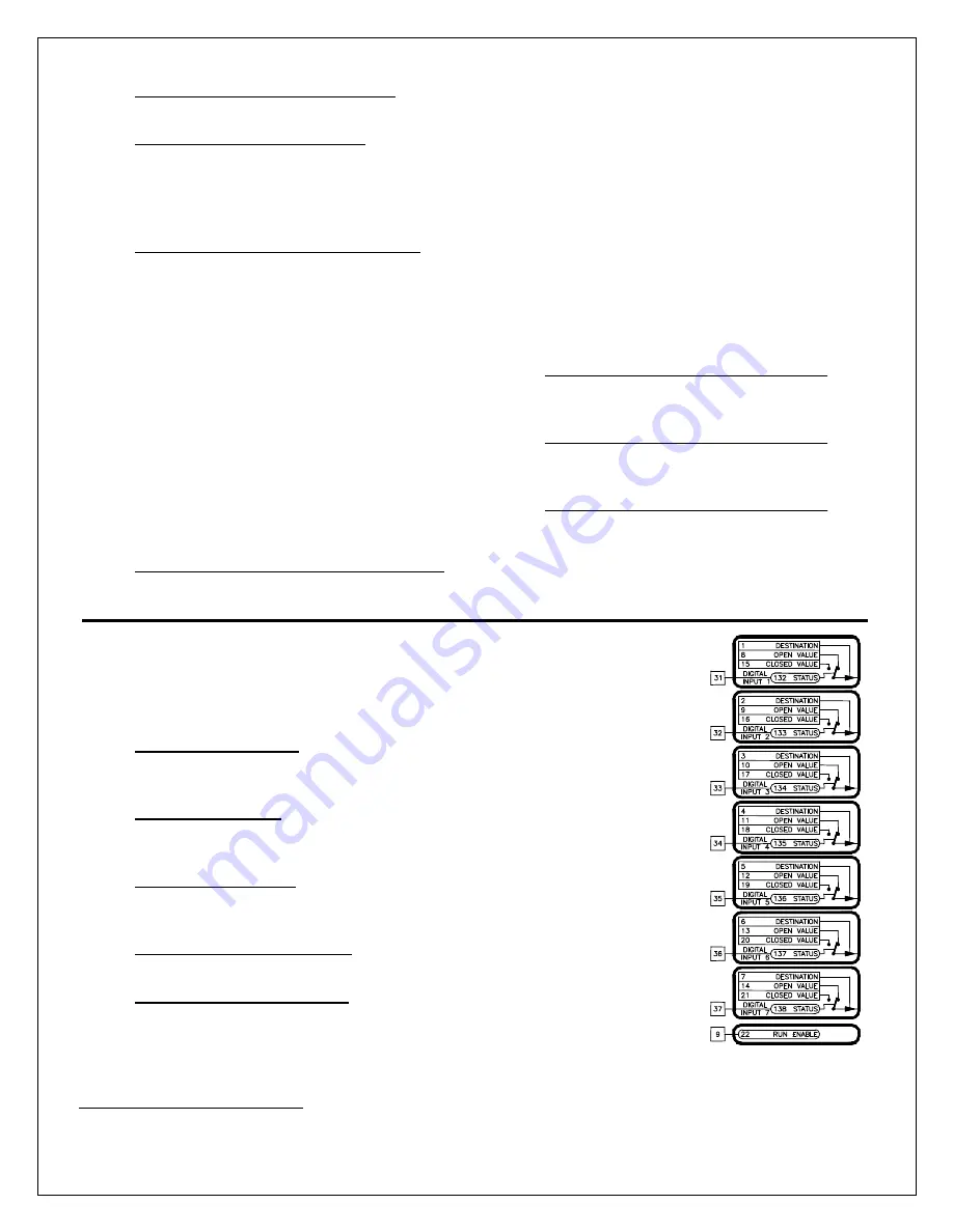
7.10 Digital Inputs Block
The Elite Pro has 7 customer configurable digital inputs. Each digital input can
write a value to any writable parameter. An additional digital input is the
Run
Permit
.
Destination (1-7, ICR)
The tag number of the parameter where the digital input information is to be
sent.
Open Value (8-14)*
When the pushbutton on the digital input is open, the value in this
parameter is sent to the destination parameter.
Closed Value (15-21)*
When the pushbutton on the digital input is closed, the value in this
parameter is sent to the destination parameter.
Status (132-138, Read-Only)
Each digital input state can be viewed for diagnostic purposes.
Run Enable (22, Read-Only)
Typically, an Emergency Stop button and motor thermostat are connected
in series to the
Run Enable
digital input. This input signals the drive to
immediately de-energize the armature contactor pilot relay and clamp all
loops.
* Note that the units and number of decimal places of this parameter will change to match that of the Destination
parameter.
Figure 17
Summary of Contents for Elite Pro EPN020-000
Page 10: ...10 Figure 4 ...
Page 80: ...80 Prints ...
Page 81: ...81 ...
Page 82: ...82 ...
Page 83: ...83 ...
Page 85: ...85 ...
Page 88: ...88 ...
Page 89: ...89 ...
Page 90: ...90 ...
Page 91: ...91 ...
Page 92: ...92 ...
Page 93: ...93 ...
Page 94: ...94 ...
Page 95: ...95 ...
Page 96: ...96 ...
Page 97: ...97 ...
Page 98: ...98 ...
Page 99: ...99 ...
Page 100: ...100 ...
Page 101: ...101 ...
Page 102: ...102 ...
Page 103: ...103 ...
Page 104: ...104 ...
Page 105: ......
Page 106: ...106 PRO SOFT ...
Page 107: ...107 WARE BLOCK DIAGRAM ...
Page 108: ...108 ...


