background image

8200-M628-O1 Rev A 

 212G/212GX Installation & Technical 

Page 36

SETUP AND CALIBRATION, Cont 

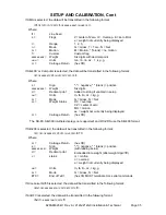
If WI110 is selected, the data will be transmitted in the following format: 


<m><sp><s>xxxxx<sp><uu><cr><lf> 

 
If number only is selected, the data will be transmitted in the following format: 


xxxxxx<cr><lf> 

 
If Toledo Short is selected, the data will be transmitted in the following format: 


<stx><swa><swb><swc>xxxxxx<cr><sum> 


Weight On Demand 

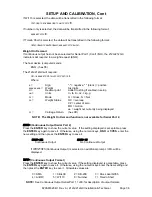
If continuous output has not been selected for Serial Port 1 (Cont1=NO), the 212G/212GX 
indicators will respond to a weight request (ENQ). 
 
The host device (computer) sends: 


ENQ - (hex 05) 


The 212G/212GX will respond: 


<s><xxxxxx><d><uu><m><cc><cr> 


 Where: 


s =  

Sign 

"-" = negative, " " (

blank

) = positive 

xxxxxx.xxx =   Weight 

Six digits  

d = 

Decimal point 

Added to string if enabled in setup 

uu =  

Units 

tn, lb, l/o, oz, t, kg, g  

m = 

Mode 

G = Gross, N = Net 

cc =  

Weight Status 

OC = overcap 
CZ = center of zero 
MO = motion 
ee = weight not currently being displayed 

cr =  

Carriage Return 

(hex 0D) 


NOTE!  The Weight On Demand function is not available for Serial Port 2. 


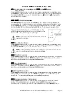
Cont2=

 (Continuous Output Serial Port 2) 

Press the 

ENTER

 key to show the current value.  If the setting displayed is acceptable, press 

the 

ENTER

 key again to save it.  Otherwise, using the numeric keys, 

0/NO

 or 

1/YES

, enter the 

new setting and then press the 

ENTER

 key to save it. 


Cont2= YES 


Cont2= NO

Continuous Output  

No Continuous Output 


If 

Cont2=YES

 (Continuous Output) is selected, an additional prompt, 

tyPE=

 will be 

displayed. 


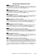
tyPE=

 (Continuous Output Format) 

Press the 

ENTER

 key to show the current value. If the setting displayed is acceptable, press 

the 

ENTER

 key again to save it.  Otherwise, using the numeric keys enter the new setting and 

then press the 

ENTER

 key to save it.  Allowable values are: 


0 = SMA 

1 = SB-400 

2 = SB-200 

3 = Rice Lake IQ355 

4 = AnDFV 

5 = WI110 

6 = Number 

7 = Toledo Short 


NOTE!

  See Continuous Output Serial Port 1, 

tyPE=

 for description of output formats. 

Summary of Contents for 212G

Page 1: ... INSTRUMENT INSTALLATION and TECHNICAL MANUAL 8200 M628 O1 Rev A 203 E Daugherty Webb City MO 64870 USA Printed in USA 09 10 Ph 417 673 4631 Fax 417 673 2153 www cardinalscale com Technical Support Ph 866 254 8261 tech cardet com ...

Page 2: ...8200 M628 O1 Rev A 212G 212GX Installation Technical Page 2 ...

Page 3: ...Figure No 9 Page 12 Main PCB Jumpers Page 13 Re Installing The Front panel Page 13 KEYPAD FUNCTIONS Page 14 DISPLAY BRIGHTNESS Page 18 ANNUNCIATOR DISPLAY Page 19 SETUP AND CALIBRATION Page 21 SETUP REVIEW Page 39 CALIBRATION C NUMBERS Page 40 ACCUMULATORS Page 40 TROUBLESHOOTING Page 41 Error Codes Page 41 Before You Call Service Page 43 CALIBRATION SEAL INSTALLATION Page 44 AXLE WEIGHER OPERATIO...

Page 4: ...C Within North America the device should be disposed of in accordance with the local laws regarding the disposal of waste electrical and electronic equipment It is everyone s responsibility to help maintain the environment and to reduce the effects of hazardous substances contained in electrical and electronic equipment on human health Please do your part by making certain that this device is prop...

Page 5: ...nge 1 0 mV min to 40 mV max with dead load boost Number of Load Cells 8 each 350 OHM minimum resistance Load Cell Cable Length 1500 feet maximum Consult factory for other requirements 30 feet maximum without sense lines Division Value 1 2 or 5 x 10 1 0 1 0 01 0 001 commercial 0 to 99 non commercial Sensitivity NON COMMERCIAL NTEP CANADA 0 15uV e 0 3uV e Class III IIIL 0 3uV e Class III IIIHD Scale...

Page 6: ...eature performs display and internal tests Auto Shutoff and Sleep modes Numeric keypad Keypad tare function Count feature with accumulator Time and Date with selectable 12 or 24 hour operation Checkweigher Three Preset Weight Comparators Axle Weigher CWL 40 Operation Mode Optional Features Analog Output Allen Bradley Interface 10 100 mbps Ethernet Adapter Additional Serial Port Checkweigher Light ...

Page 7: ...utermost edges NEVER touch the components component leads or connectors ALWAYS observe warning labels on static protective bags and packaging and never remove the card or component from the packaging until ready for use ALWAYS store and transport electronic printed circuit cards and components in anti static protective bags or packaging Environmental The Cardinal 212G 212GX indicators meets or exc...

Page 8: ...sibility of the customer to have a qualified electrician install the proper power cord plug which conforms to national electrical codes and local codes and ordinances The AC power outlet for the 212G 212GX indicators should be on a separate circuit from the distribution panel This circuit should be dedicated to the exclusive use of the indicator The wiring should conform to national and local elec...

Page 9: ...aser to file all claims for any damages or loss incurred during transit Mounting The Model 212G 212GX indicators are housed in a thermoplastic enclosure The gimbal may be mounted on a desktop or other smooth flat horizontal surface or may be mounted on a wall Refer to Figure No 1 for a layout of wall mounting bolts If wall mounted make certain the mounting surface is strong enough to support the i...

Page 10: ...8200 M628 O1 Rev A 212G 212GX Installation Technical Page 6 INSTALLATION CONT Figure No 2 ...

Page 11: ...tor and into the enclosure 4 Remove 4 inches of the outer insulation jacket 5 Next remove 1 4 inch of insulation from each of the 4 wires and shield without sense leads or 6 wires and shield with sense leads 6 Referring to the table below or on the circuit board for terminal connections connect each of the wires to terminal block P7 Refer to Figure No 9 for terminal block location 7 To terminate a...

Page 12: ...llations with over 30 feet of cable between the indicator and the load cells sense wires should be used The sense wires must be connected between the SENS SENS terminals on the indicator and the EXCITATION EXCITATION wires of the load cells or the SENS SENS terminals of the load cell trim board or the section seal trim board Figure No 4 ...

Page 13: ...r to Figure No 2 for the gland connector layout 3 Slip the serial cable through the gland connector and into the enclosure 4 Remove 2 inches not 5 to 6 inches of the outer insulation jacket 5 Next remove 1 4 inch of insulation from each of the wires 6 Connect each of the wires to the Serial I O terminal block P11 referring to Figure No 9 for terminal block locations 7 To terminate a wire use a sma...

Page 14: ...the 212G 212GX indicators to supply source 12 VDC to a solid state relay or other load of 200 ohms or greater To operate from the 12 VDC source the positive connection from the relays must be connected to the PWC connector pins and the negative wire from the relays to the GND pin See Figure No 9 for jumper and REMOTE OUTPUT connector location For completely isolated outputs J11 must be open positi...

Page 15: ...pen at weights under the preset weight then switch at the preset weight from on to off or off to on by setting the under weight condition to on or off during setup and calibration or setup review Refer to the Setup and Calibration d out Digital Output section of this manual for more information EXAMPLE d oUt 1 1 The PWC1 relay is on closed for weights under the preset weight and off open for weigh...

Page 16: ...8200 M628 O1 Rev A 212G 212GX Installation Technical Page 12 INSTALLATION CONT Main PCB Figure No 9 ...

Page 17: ... loads less than 10 of the combined load cell capacity connect the dead load boost jumper J10 on the printed circuit board J11 PWC SRC SOURCE The J11 jumper when connected closed supplies 12 VDC from the 212G 212GX indicators to a solid state relay or other load of 200 ohms or greater When J11 is open positioned on one plug in pin only or removed the 12 to 24 VDC must be provided from an external ...

Page 18: ...oint HOLD KEY Pressing the HOLD key will lock the weight and display HOLD on the right for the 0 8 LCD display and turn on the HOLD annunciator on the 2 display The HOLD is only available if LFT NO in SETUP COUNT SAMPLE KEY This key performs two functions The first time it is pressed the indicator will count unless piece weight is 0 The second time it is pressed or if pcwt NO on the first press wi...

Page 19: ...ES setting the date format is month day year 24 Hour Format Selected In Setup td 24 1 With the display showing HoUr press the ENTER key 2 If the time displayed is correct press the ENTER key and proceed to step 4 3 If the displayed time is incorrect use the numeric keys to enter the correct time and press the ENTER key Note that with the 24 hour format selected entering all times after noon 12 00 ...

Page 20: ...how PSET3 if 3 active presets were selected in SETUP Press the ENTER key and the currently stored value for the number 3 preset weight comparator will be displayed As before if the value displayed is acceptable press the ENTER key otherwise use the numeric keys to enter the new value and press the ENTER key Checkweigher Can be used with 2XX OU Checkweigher Light Bar Option If the Checkweigher feat...

Page 21: ... tickets in addition to the standard print tab settings These tickets are designed by the Cardinal Scale s PC based programs Visual Print or nControl and then downloaded to the indicator During operation the print formats are selected by using the and PRINT keys in combination refer to the next section for details NOTE When the PRINT key is pressed the indicator looks for the selected format If th...

Page 22: ...ing setup and calibration as well as during normal operations and are also used to answer yes 1 YES or no 0 NO to various prompts ENTER KEY This key serves two purposes First when reviewing setup parameters pressing the ENTER key will display the current setting of the parameter Second the ENTER key is used to signal completion of the entry of data and causes the indicator to process the data ente...

Page 23: ...then the PRINT key will display a prompt Prt Press the ENTER key to show the current value If the setting displayed is acceptable press the ENTER key again to save it Otherwise using the numeric keys enter the new setting and then press the ENTER key to save it Allowable values are 0 print tab settings 1 visual ticket format 1 2 visual ticket format 2 In addition to using the and PRINT key combina...

Page 24: ...y removing the 12 access screws on the front panel Refer to Figure No 11 Enter Setup Mode 1 With the 212G 212GX indicator OFF 2 Remove the front panel 3 With the 212G 212GX indicator ON press and release the calibration switch Refer to Figure No 11 4 The SETUP menu prompt will be displayed 5 Continue to press and release the switch to step to the beginning point for other menus MENUS SEtUP Setup M...

Page 25: ...at any time press the ON OFF key twice SEtUP USA Domestic or International With SEtUP displayed press the ENTER key The display will change to USA Press the ENTER key to show the current value If the setting displayed is acceptable press the ENTER key again to save it Otherwise using the numeric keys 0 NO or 1 YES enter the new setting and then press the ENTER key to save it USA YES Domestic USA N...

Page 26: ...ble press the ENTER key again to save it Otherwise using the numeric keys 0 NO or 1 YES enter the new setting and then press the ENTER key to save it LFt YES LFt NO Interval Settings Int allowed are 1 2 5 10 20 50 Interval Setting Int is selectable from 1 to 99 NOTE When both LFt YES and USA YES the followings results occur Scale must have between 100 and 10 000 divisions Tra 5 or 0 to 3 Inhibit s...

Page 27: ...8200 M628 O1 Rev A 212G 212GX Installation Technical Page 23 Lamp test on power up ...

Page 28: ... the new setting and then press the ENTER key to save it Allowable values are 0 1 2 or 3 0 XXXXXX 2 XXXX XX 1 XXXXX X 3 XXX XXX CAP Capacity Press the ENTER key to show the current value If the setting displayed is acceptable press the ENTER key again to save it Otherwise using the numeric keys enter the new setting and then press the ENTER key to save it Allowable values are 1 through 999 999 NOT...

Page 29: ...se the numeric keys to select the format 12 or 24 hour clock operation and then press the ENTER key to save it Note that in the 24 hour format 12 is added to all times after noon i e 3 PM would be 1500 td 12 td 24 12 hour clock 3PM displays 3 00 24 hour clock 3PM displays 15 00 D oUt X Y Digital Output Press the ENTER key to show the current value If the setting displayed is acceptable press the E...

Page 30: ...on Accept Disabled SLEEP Sleep Mode Feature The Sleep Mode feature conserves battery power when the indicator remain unused for a selected period of time With the feature enabled the load cell excitation will be reduced and the display will be blank Press the ENTER key to show the current status of this feature If a number other than 0 is shown this feature is selected and the number shown corresp...

Page 31: ...o below zero weight of container and is then reset to zero 5 Operator is required to repeat step 1 before next weighing operation id ID Prompt The id ID prompt enables an ID prompt before printing a ticket With the display showing id press the ENTER key to show the current value If the setting displayed is acceptable press the ENTER key again to save it Otherwise using the numeric keys 0 NO or 1 Y...

Page 32: ...s the ENTER key to save it Allowable values are 0 1 2 or 3 Note that if you select 3 Custom Filtering two additional prompts will be displayed dFLt 0 Disabled NO Filtering 1 MINIMAL FILTERING sample rate 2 2 MODERATE FILTERING sample rate 1 3 CUSTOM FILTERING NOTE The prompts F Filter Level and b Break Range will only be displayed if you selected 3 Custom Filtering for the dFLt Digital Filtering p...

Page 33: ...55 FILTER SETTING RECOMMENDATIONS Non Critical Sample Rate If the sample rate is not critical as in static weighing set dFLt to 0 no filtering dFLt 1 F 6 b 12 Sr 2 Sec or dFLt 2 F 6 b 8 Sr 1 Sec Critical Sample Rate If the sample rate is critical as in a filling operation use the Custom Filtering set dFLt to 3 1 Sr SAMPLE RATE 1 to 100 samples second determination Set the sample rate as close as p...

Page 34: ...1 and CAL2 The value of the test weight is entered when CAL1 is displayed and the NET GROSS key is pressed when CAL2 is displayed 3 Single Point for Span Only Last Zero This calibration method requires one test weight and establishes a new conversion factor span without affecting the zero calibration value stored during the last calibration This minimizes placing and removing test weights and is e...

Page 35: ...roceeding right a series of dashes will appear on the display The dashes will stay on the display momentarily then disappear after which the display will show CAL2 CAL2 SECOND CALIBRATION WEIGHT The display will show CAL2 0 This is the second of two calibration weights This weight could be ZERO NO LOAD or the TEST WEIGHTS TEST LOAD If the second calibration weight is to be ZERO NO LOAD press the E...

Page 36: ...left When large values are used more than 3 digits the CAL1 prompt will automatically scroll off the left side of the display to show the additional digits on the right as they are entered Starting at the left and proceeding right a series of dashes will appear on the display The dashes will stay on the display momentarily then disappear after which the display will show CAL2 CAL2 SECOND CALIBRATI...

Page 37: ...of two calibration steps Remove the weights on the scale platform and then press the ZERO key The display will advance to Sio Single Point for Zero Only Only Zero Calibration CAL1 FIRST CALIBRATION WEIGHT The display will show CAL1 0 This is the first of two calibration steps Insure the scale is empty Press the ENTER key Starting at the left and proceeding right a series of dashes will appear on t...

Page 38: ...ENTER key to show the current value If the setting displayed is acceptable press the ENTER key again to save it Otherwise using the numeric keys enter the new setting and then press the ENTER key to save it Allowable values are 7 or 8 StoP Serial Port Stop Bits Press the ENTER key to show the current value If the setting displayed is acceptable press the ENTER key again to save it Otherwise using ...

Page 39: ...f enabled in setup uu Units tn lb l o oz t kg g m Mode G Gross N Net cc Weight Status OC overcap CZ center of zero MO motion ee weight not currently being displayed cr Carriage Return hex 0D The SB 80 SB 300 multiple displays not supported and WinVRS use the SB 400 format If SB 200 is selected the data will be transmitted in the following format cr s xxxxxx d c uu m ETX Where cr Carriage Return he...

Page 40: ... OC overcap CZ center of zero MO motion ee weight not currently being displayed cr Carriage Return hex 0D NOTE The Weight On Demand function is not available for Serial Port 2 Cont2 Continuous Output Serial Port 2 Press the ENTER key to show the current value If the setting displayed is acceptable press the ENTER key again to save it Otherwise using the numeric keys 0 NO or 1 YES enter the new set...

Page 41: ...ss the ENTER key again to save it Otherwise use the numeric keys to enter a new setting and then press the ENTER key to save it Allowable values are 1 or 2 NOTE Although either port can be used for the printer port it is recommended to use the bi directional port 1 with a bi directional cable HoUr Time Print Location Press the ENTER key to show the current setting for the location of time printing...

Page 42: ...cation Press the ENTER key to show the current setting for the location of Net weight accumulator printing If the setting displayed is acceptable press the ENTER key again to save it Otherwise use the numeric keys to enter a new location and then press ENTER to save it CoUnt Count number of pieces on the scale Print Location Press the ENTER key to show the current setting for the location of Count...

Page 43: ... unit off then all OFF weighing unit ON Press the 1 YES to increase the span OR press the 0 NO key to decrease the span Press the key to return to the previous prompt or press the ENTER key to exit FSPAn and return to the SetUP menu With the FSPAn prompt displayed after pressing the Calibration switch With FSPAn displayed place a calibrated test weight on the scale and press the ENTER key After pr...

Page 44: ...ort Selection Time Date Consecutive Number Gross Weight Tare Weight Net Weight Gross Weight Accumulator Net Weight Accumulator Count Piece Weight To enable the Setup Review feature with the indicator ON 1 Press the key The indicator will respond by showing the FunCt Function prompt and alternately flashing off and on all ON weighing unit off then all OFF weighing unit ON the annunciator display 2 ...

Page 45: ...nt the NET accumulator 1 Press the key the NET GROSS key and then the PRINT key 2 The indicator will return to normal operation when printing has been completed To clear zero the NET accumulator 1 Press the key the NET GROSS key and then the ZERO key 2 Press the key to return to normal operation To view the Gross accumulator 1 Press the key and then the NET GROSS key twice 2 Press the key to retur...

Page 46: ... button tare value of a negative value C ENTER key pressed to enter a tare weight value that exceeds the scale capacity D ENTER key pressed to enter a tare weight value that is inconsistent with the scale division value i e attempt to enter a tare of 123 with scale divisions of 5 E ZERO key pressed when the gross weight is outside the scale zero weight range F lb kg key pressed to change to kg whe...

Page 47: ...e over capacity load from the scale platform May indicate miscalibration oF Overflow The indicator is attempting to display a positive number greater than six 6 digits in length or a negative number of more than five 5 digits CORRECTIVE ACTION Return to Gross Weight mode and review Tare value May indicate miscalibration toobiG UNITS key pressed in an attempt to perform a unit conversion where the ...

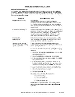
Page 48: ...ollowed Indicator will not display weight Refer to Error Codes section and make certain that the oCAP message is not displayed If so and scale is not loaded perform the calibration sequence The printer prints but does not use the Print Tab Settings or prints a test ticket The print tab setting or visual ticket format must be selected prior to beginning the weighing operation or just prior to print...

Page 49: ...rument is used in a commercial application it must be tested and sealed by your local weights and measurements official The 212G 212GX has been designed to accept a lead and wire security seal to prevent unauthorized access to the calibration adjustments Refer to Figure No 12 for details on the installation of the seal Figure No 12 ...

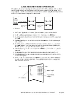
Page 50: ...rve the weight of the first axle and press the PRINT key to record the weight date and time 5 Have the vehicle pull forward until the next axle is on the center of the wheel load weighers NOTE If the next axle is a tandem or tridem set of axles place ONLY the first axle of the group on the wheel load weighers 6 Observe the weight of this axle and press the PRINT key to record the weight date and t...

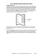
Page 51: ...that the next two axles form an axle group whose total is to be recorded The example below illustrates the print format when the two axle groups are identified 13 47 09 26 10 1 15440 lb 2 16320 lb 3 15980 lb 2 3 32300 lb Axle Group 4 15880 lb Totals 5 15700 lb 4 5 31580 lb Total 79320 lb Note that there is a maximum of 9 single axles in an axle group and that the axles must be weighed in a consecu...

Page 52: ...8200 M628 O1 Rev A 212G 212GX Installation Technical Page 48 ...

Reviews: